|
Gun Description
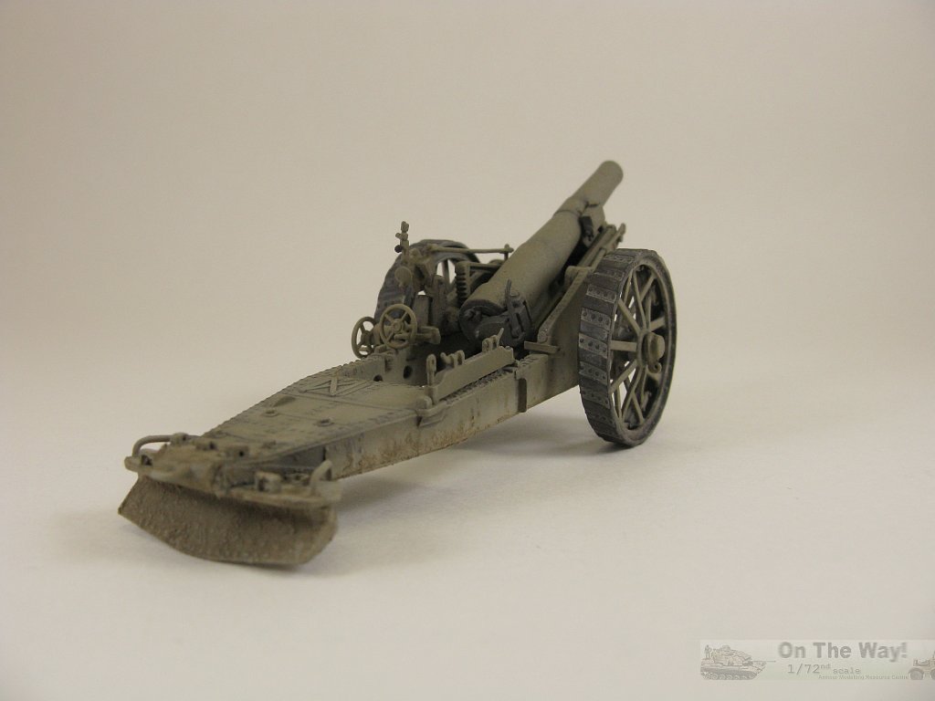
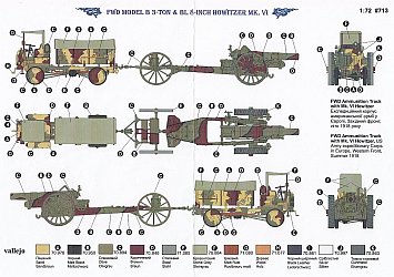
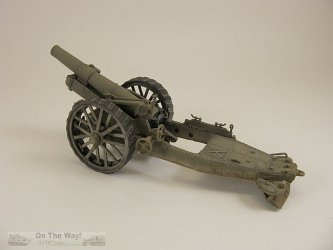
From the instruction sheet: "In 1915 the British Vickers engineering company designed anew 8 inch caliber gun, the BL Mk VI howitzer. It was essentially a
constructive modernization of the previous Mk V, the primary improvements concerning the hydraulic recoil mechanism of the barrel of the gun. In fighting situations
the sector of firing amounted to 4 degrees to the left or to the right, and up to 50 degrees elevation. The static part of the gun had a new, more modern look. The
firing range of a shot could reach nearly 10 kilometers, while the gun's weight in comparison with the previous version was more than three tonnes lighter.
For towing the gun to fighting positions it was connected with a bulky forward part, the limber, which was hauled by a heavy transporter such as the FWD truck or
a Holt 75 tractor."
The shell weighed 200 lbs. Reload required the barrel to be brought to zero which limited the rate of fire to 1 round per minute. The gun was used by
British Commonwealth forces, France and the USA during WW1. It was also manufactured in the USA and examples saw use with the Finns
as the 203 H/17 during their Continuation War with the Soviet Union.
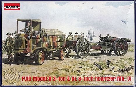
The kit
I bought this combination set of gun, limber and FWD truck, instead of Roden's offering of the gun only (kit no. 716), with the thought of
building the gun & limber, and eventually constructing the FWD as a civilian vehicle.
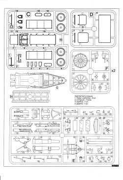
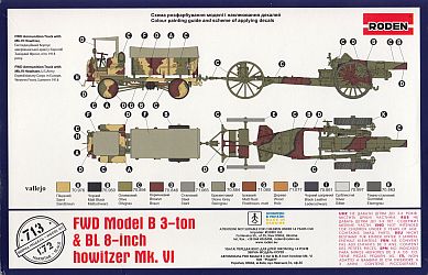
Inside the box you get six sprues moulded in a softish green styrene
like plastic. The gun parts cover three of those plus a separate carriage part and a set of two vinyl like treads. There is an 10 page instruction sheet with colouring
guide, plus an identical colouring guide on the box's rear panel. This review only covers the howitzer and limber as described on page 8 of the instructions.
Inspection of the sprues revealed a plethora of flaws: seams everywhere, mold shift, poorly
cast detail (e.g. most of the rivets were nothing more than a microscopic bump in the plastic), ill fitting parts, ejector pins in the most obvious of places and
where their removal guaranteed erasing adjacent detail in the area and vague instructions. The final indignity came with the realization
that the instructions missed a couple of steps. I clued into that problem as I proceeded with the build and noticed that there were numerous parts left on the
trees that hadn't been called out in the assembly
diagrams. I had to locate Roden's 1/35 instructions (kit no. 813) plus the instructions for their 1/72 stand alone kit to
discover where these leftover parts went.
Even with those I still needed numerous reference pictures to make sure parts went in their proper location because I no longer trusted "Rotten's" instructions.
The aforementioned mold shift, seam removal and the poor rivet molding forced me to find parts in my spares box for items like the control wheels and to
replace almost every rivet using Archer decals (Rivet Fastener Heads Rivets/Screws 0.011" (0.28mm) diameter, item no. AR88015).
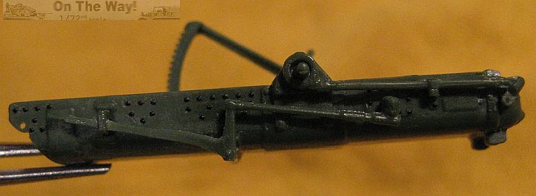
Now that I've described the mess, below is what I did to rectify it somewhat. This review will be a step-by-step account following Roden's instructions along with
the missing step provided via Roden's other howitzer kits in 1/72 and 1/35 scale.
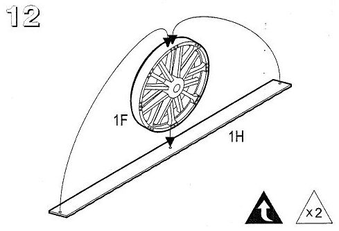
Step 12
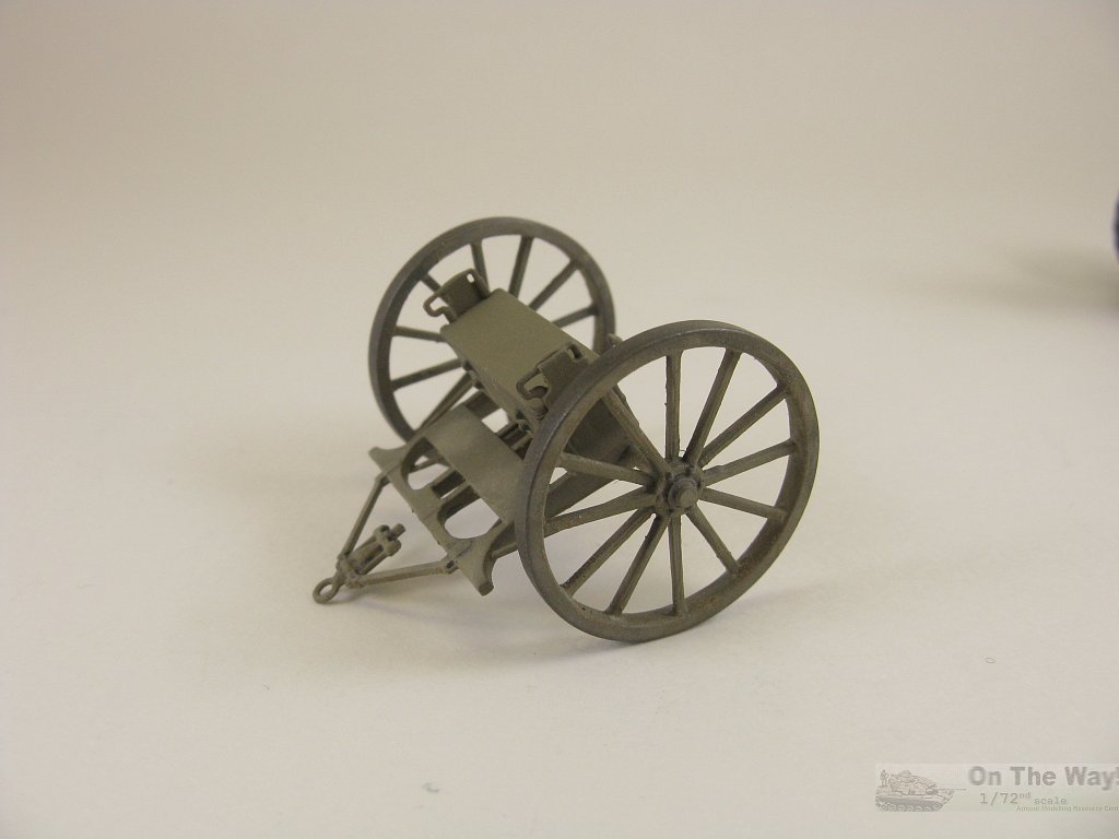
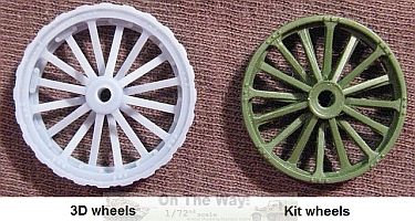
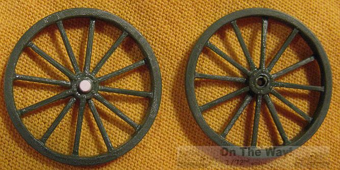
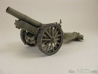
You may notice that the wheels I used are not those that come in the kit. Their poor molding looks nothing like the real thing and the terrible vinyl style
tread is ugly and would most likely not take any type of glue very well. I have Will Alcott to thank for 3D printing one-off custom replacements. They emphasize
just how bad the kit's wheels are and markedly change the look of the gun for the better (comparison photo below).
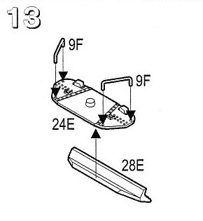
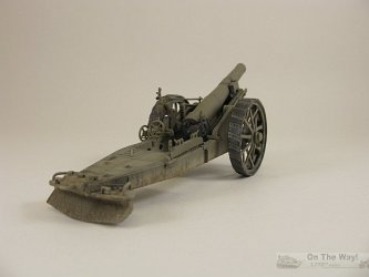
Step 13
This step builds the trail's spade. All detail on the top side was removed and replaced. This included rivets (decals), grab handles (copper wire) and bar brackets (plastic
channel & strip). I didn't attempt to add the lip seen on the real gun lip that runs around the circumference of the horizontal plates. The underside of the spade that
digs into the earth had rivets added to match those on the upper side. Surprisingly, the spade to trail join was the best fit of the whole the build.
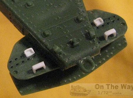
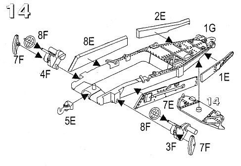
Step 14
This step was done after Step 16 and took the most work and time to finish.
- I strongly suggest adding the front towing hook (part 5E) at the last in Step 17. It is exposed and I broke it off while
working my way through construction.
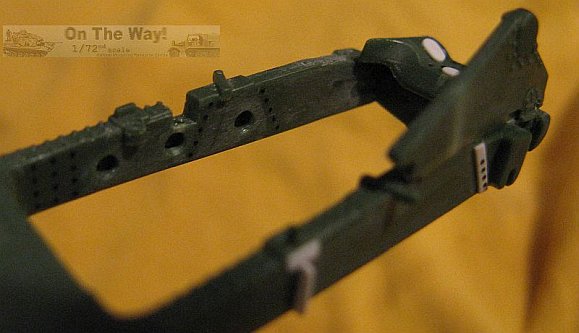
- All rivets were sanded off and replaced.
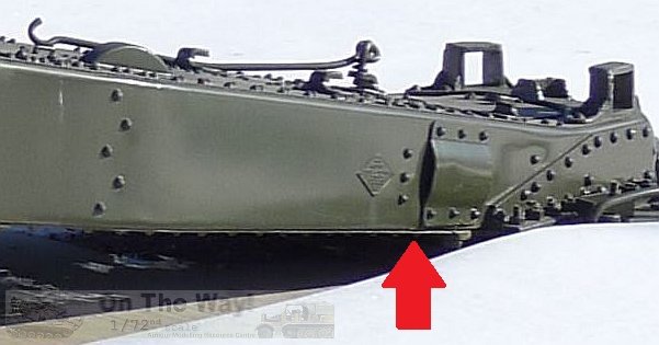
- There are three large and very obvious holes on the inside of each trail arm that Roden didn't deem significant enough to add.
They were made by using
the kit's inserts (parts 7E & 8E) as templates to fashion cardboard copies, then measuring out the spacing of the holes & drilling a small hole at each
point on the template, and finally
positioning the templates on the trail and marking where to drill using a small tipped marker pushed through the template's holes.
- The inserts for the side of the trail (parts 1E, 2E, 7E & 8E) are too wide and extend below the trail's lower edge, so they
were sanded flush
to the trail bottom and the seam filled, which also conveniently filled the deep ejector pin marks found here. Be careful when gluing the inserts to the trail as
they need to bend around a slight curve and could snap if not glued in small increments, allowing time for the glue to set in between applications.
- The outer detail on inserts 7E & 8E was removed and replaced using rivet decals and plastic strip pieces.
- Pictures of the real gun show that the trail's outer face lacked seams so they were all filled.
- Inspect the instructions closely, otherwise it may be difficult to add parts due to others being in the way, e.g. add parts
32E & 33E (shown in step 17) before parts 3F, 4F & 7F.
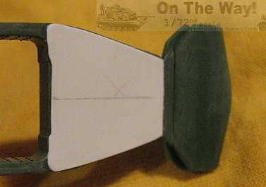
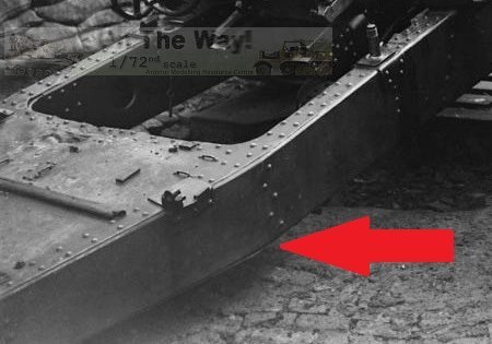
- I had my doubts as to the veracity of the kit's hollow area under the trail's rear. I discovered evidence that
this area should be covered, based on closeups of trails found at [5]. A scratch built piece was cut from plastic sheet. Topside rivets and cross braces were mirrored
as best as I could on the new scratch built cover piece using Archer decals and plastic strip. It may not be 100% correct but it definitely beats
having an ugly void under there.
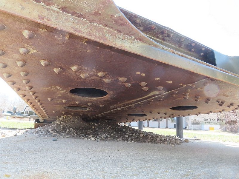
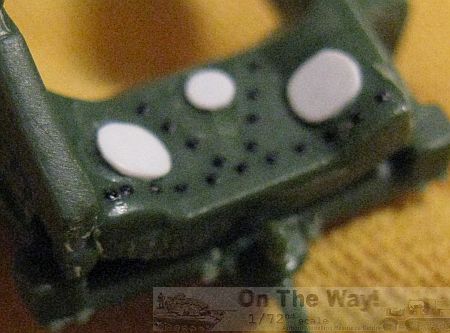
Addendum: 2025/07/14
I finally got an opportunity to visit the Royal Canadian Artillery Museum, located on the Canadian Forces Base Shilo in southern Manitoba, and took some photographs
of the rear portion of this gun's trail underside. As I had surmised above, this area is covered. A surprising discovery though was the presence of six holes drilled
here as well, as seen in the photos below.
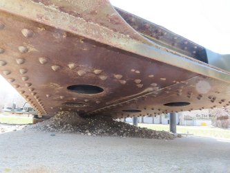
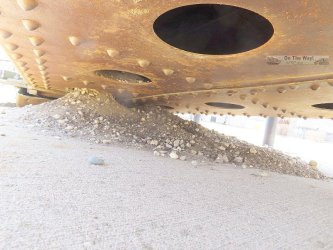
Each one appears to be centred within its respective set of interior braces. I was unable to squeeze underneath to measure their diameter though,
so that will still be a guess on the part of the modeller. So, anyone wishing to super detail this gun,
whether it be in the one true scale of 1/72, or any of the other infidel scales, they will need to add not only the missing panel, but the holes as well.
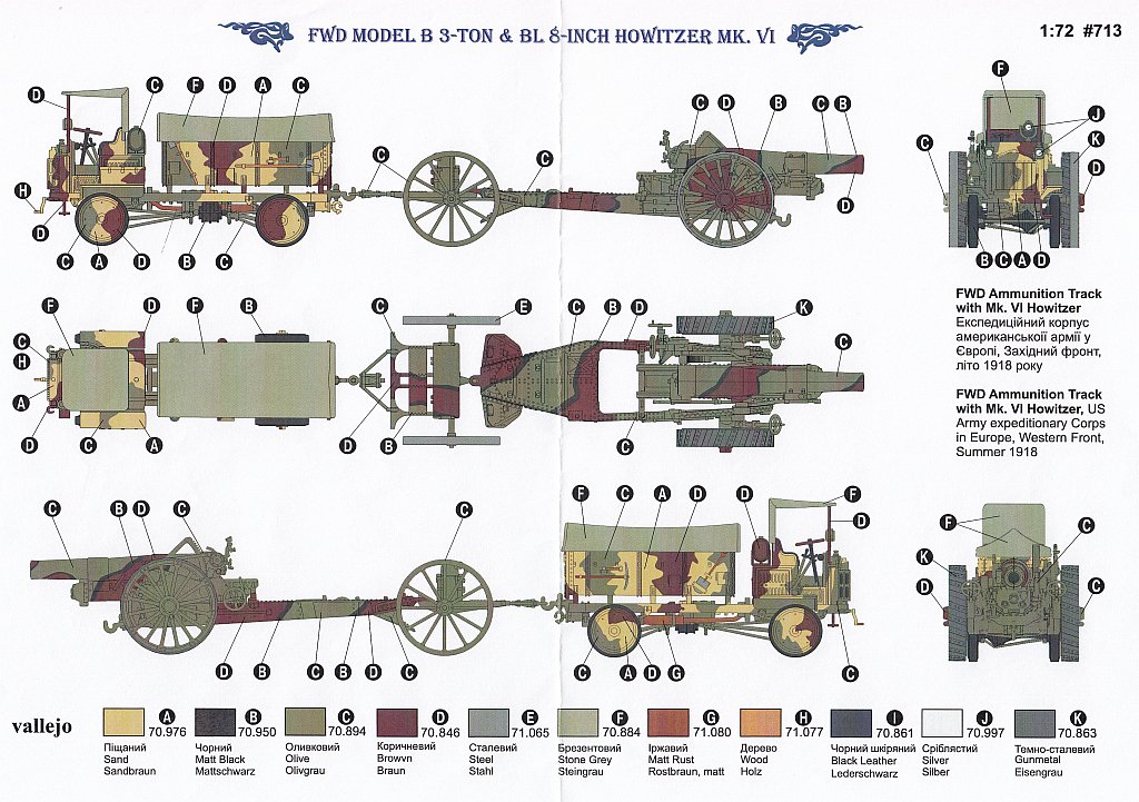
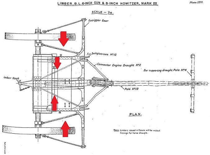
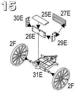
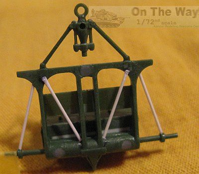
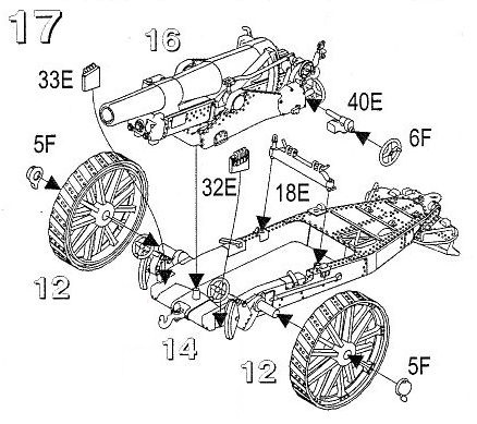
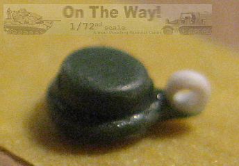
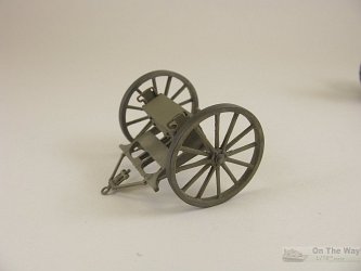
Step 15
The limber was mostly built as per instructions. There were a trio of significant ejector pin marks of approximately 2mm in diameter and 1mm deep that need filling on
the underside of the axle/chassis (part 31E); one near each end of the axle and one near the front cross bar. The seat is moulded hollow and that was filled.
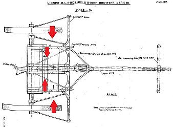
Some lengths of round rod supplied missing detail as per the red arrows in the diagram immediately below (from [3]). The axle ends were exposed when inserted in
the hubs so caps were punched from plastic sheet.
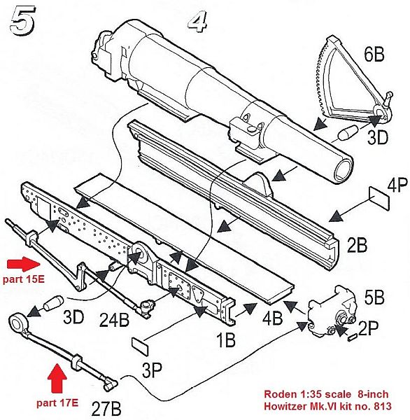
Step 16
This step was done before Step 14. I thought it best to assemble the barrel first so it would help with aligning the recoil slide's walls and floor, plus
the finished sub-assembly may help later with alignment of the trunnion walls on the carriage. At this time
I hadn't realized Roden had missed parts for this
assembly. They were added afterwards using their 1/35 scale instructions as a guide (see diagram below right: red arrows & part numbers identify the corresponding
1/72 scale kit parts).
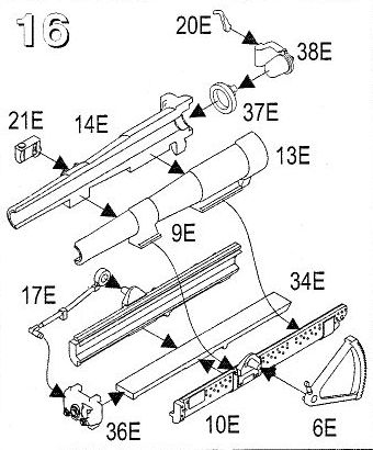
- Part 6E, the elevation gear, needs a hole drilled to slip over the trunnion pin.
- Two small plastic disks were added to represent the breach screw's hinge pins - top and bottom of part 38E.
- All rivets were sanded off and replaced. The seams on the underside of the slide were filled to replicate that of the real gun.
- Inserting part 37E into the rear of the breech, deformed it into an oval. Fortunately, the breech screw covers that
defect.
- Part 21E had a small sink mark to fill. Disks punched from plastic sheet replaced some of the soft detail.
- Instructions go from Step 16 (assembling the barrel and slide) directly to adding it along with the trunnion walls in Step 17, but
there's nothing showing what pieces go on the trunnion walls and which part numbers to use, hence my addition of the following step that should have been included
in the instructions.
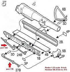
Step 16, part 2 (taken from kit no. 716)
Below left is the diagram taken from Roden kit 716 that was absent from this kit's instructions.
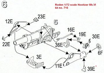
- Part 16E was left off until final assembly.
- The small hole at the top of part 22E was drilled out.
- Detail on top of part 3E was replaced and it was glued to the trail in this step to aid alignment of the trunnion walls, which
were also added to the trail at this time. I sandwiched the barrel/slide assembly between the trunnion walls but did not glue it in place, so that it could move
up and down for
access to the underside of the barrel/slide assembly with an airbrush. Take your time here and test fit often. The parts don't fit well and any misalignment of
the walls will be painfully obvious later.
- All rivets on the trunnion walls (parts 11E & 12E) were replaced with one compromise. The top edge of the trunnion walls
have two lines of parallel and tiny rivets which are well moulded here. Unfortunately there was a seam running between them. To eliminate the seam meant removing
the rivets, and as the width here is just a millimetre wide or so, getting two lines of decal rivets on this surface was next to impossible. I settled on one line only.
- Part 39E doesn't look anything like what's depicted in the instruction's diagram. You'll need to fiddle around to get it placed
properly to accept the shaft on part 40E (added in step 17).
- Both aiming wheels (part 6F) were replaced (other wheel is in step 17). This wheel had a handle added and its shaft replaced.
Step 17
This where the sub-assemblies come together. It's best to leave the wheels off here and add them after painting.
- Instructions show the travel lock (part 18E) spanning the gap in the spades. Attach it thus for travel mode, mount it
across the two holes on the right topside of the trail as I did, or leave it off, as many period photos show it missing while the gun is emplaced.
- The poor detail on the howitzer's hub cap tie down loops was redone. I also added a disc punched from plastic sheet to the back to
help center it onto the wheel hubs.
- The shaft on part 40E was replaced with plastic rod. Its mounting tab is smaller than the receiving slot so some filling of a gap is
required here.
- A problem was encountered with the wheel brakes (part 7F) as they wouldn't fit inside the 3D wheel's inner rims.
Sanding off a good portion of their face fixed that issue. The brake pads also don't quite sit completely inside the wheel due to the wheel rim's lack of width here. This small
issue was ignored since these wheels make such a huge improvement to the overall look of the gun. I tested, and the kit wheels fit without problems though.
 This little connecting fillet
was added to the rear end edge of the right trunnion wall. This little connecting fillet
was added to the rear end edge of the right trunnion wall.
|
Final prep, painting & final assembly
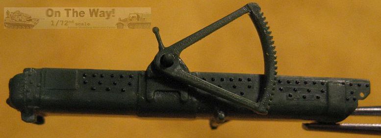
As seen in my build photos above, all rivet decals were applied directly to bare plastic. Copious applications of Microsol setting solution got them to
snug down tight. By applying them to plastic directly, it almost guarantees no possibility of the carrier
film being evident after a few coats of paint plus gloss & matte coats. I prefer washing my models prior to painting, thus the rivets were coated with brush
applied Microscale Glosscote to prevent them from being lifted by the water and dish soap.
Will's 3D wheels were a tight fit right from the start. They had to be reamed some to fit the axles after painting was completed.
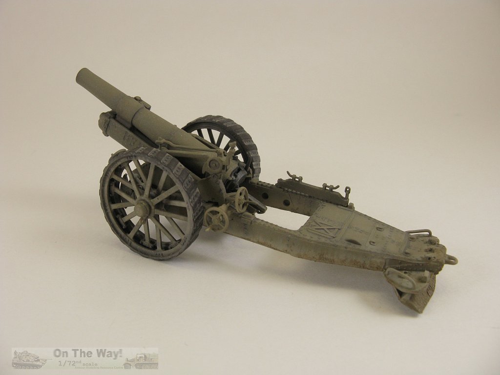
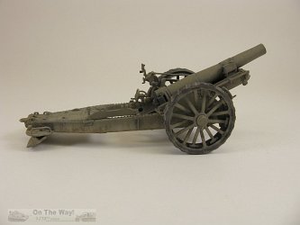
Conclusion
Egad, this kit turned out to be a real dog's breakfast - not the mess created by the dog eating the same, but more like the mess after said breakfast has been processed
and exited the dog's rear! The soft detail, atrocious instructions, chronic poor fit and plethora of molding flaws, makes building this kit into an acceptable
display model, a chore.
After the trial and tribulations with the gun & limber, I'm skeptical the truck will prove any better build wise. It will most likely suffer the fate of being parted out to
my spares boxes. I do have to admit though, that after all that work, the model does make into a respectable scale representation of this brutish looking gun.

References
[1] scalenews.de
[2] landships (Mk.VI)
[3] landships (Mk.XIX)
[4] wikipedia
[5] silverhawkauthor.com
Review sample purchased by the author.
Roden products are available at

|