| --Flyhawk |
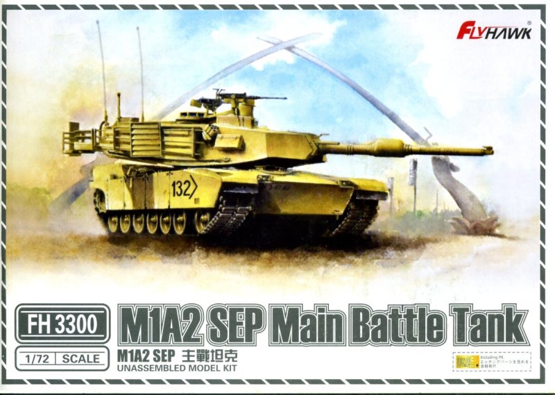
M1A2SEP Main Battle Tank |
|||
Kit : # FH3300 |
Review by F. Giovagnorio |
|||
| --Flyhawk |
M1A2SEP Main Battle Tank |
|||
Kit : # FH3300 |
Review by F. Giovagnorio |
|||
 |
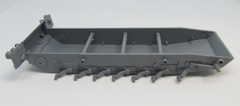
As every Flyhawk kit, this one too should be faced with a certain degree of respect, which means that the construction should be accurately planned, taking into account the necessity of avoiding that some particulars might become hidden during a careless construction so that they will be impossible to paint lately. For this reason, I identified four main sub-assemblies, and my construction review is based on this personal approach, which, needless to say, might not be the best one. I: lower hull with back plate and lateral walls The construction of sub-assembly I is the subject of Step 1 in instruction manual: mounting the wheels and tracks right now, as you should do according to the instructions, would give you troubles during the painting stage because they will be covered by the lateral skirts (but you can mount the return rollers, as they have no rubber rim; in the finished model they will be invisible anyway). The way the kit is engineered lets you position the wheels and tracks later. About the wheels and tracks, I would suggest two alternative approaches: the first one, paint each element separately and glue everything in place before assembling the lateral skirts; the second one, insert, but do not glue, each wheel to road arms and inner part of drive sprocket to its hole and then glue inner tracks to road wheels and sprocket; later, glue outer road wheels, outer drive sprocket and outer track, then remove the whole assemble for easier painting. The manual is very detailed and extremely clear, so it can be followed as-is. Some pieces must be carefully placed and rotated to give them the right alignment, as pegs&holes will not help you in that (for example, the tail lights - pieces K-11 and K-32 - and the external phone - piece L-2). Needless to say, fitting of parts is exceptionally planned, but some care is required anyway. Flyhawk provides three square plastic rods (E-3) to be placed between the lateral walls: they give stability to the lower plate-lateral walls complex and assure that the angles between the lower plate and each lateral wall are exactly 90 degrees. One last, little thing to do before calling this stage finished: drill two small holes in the rear towing shackle inserts, something that it is strangely missing while being present in the front insertion points. Anyway, Flyhawk provides no towing shackles, which is not a serious mistake because apparently not every tank carries them.
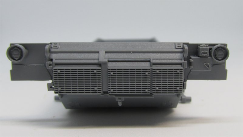
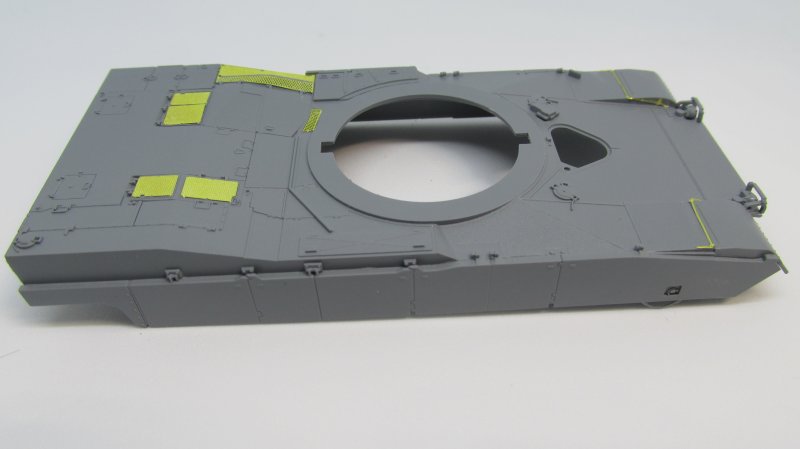
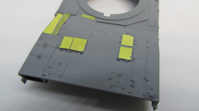
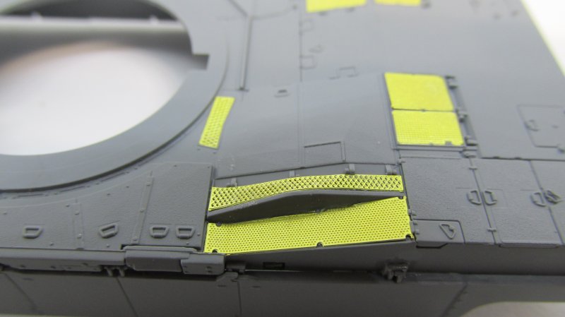
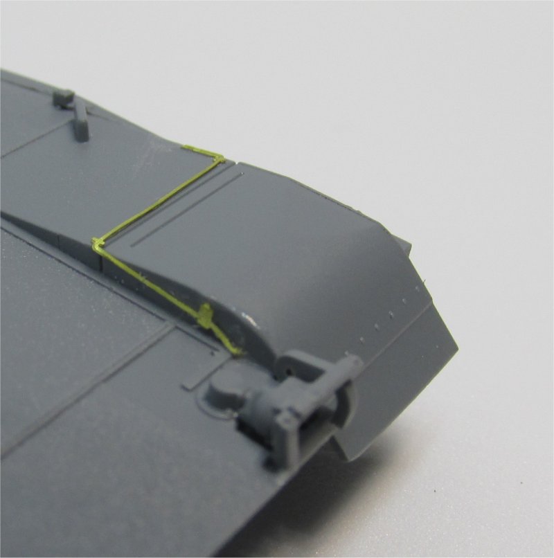
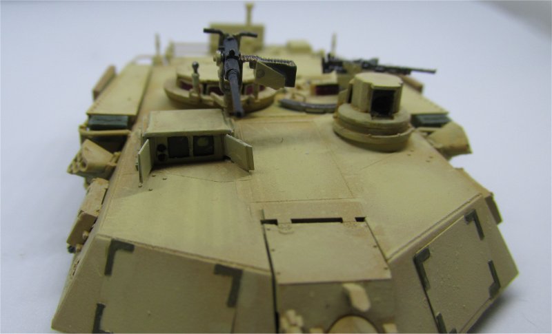
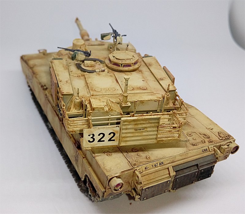
II: Upper hull with side skirts Not much to be said in Step 2, just follow the instructions. Some care with positioning the 7 screens for the rear engine deck (I must observe that this is one of the points where this Flyhawk kit surpasses any other M1 Abrams kits), a really nice touch because they are very finely designed and go into place rather easily; the inner of the 2 left screens must be placed on a sloped surface, so it must be bent accordingly. Other PE parts for the upper deck include the bar for the front fenders and the grab handle on the left side. The side skirts can be assembled now or left off and glued later after having installed the track assembly. Observing pictures of real vehicles, you can note that there is a missing details: a sort of semi-circular protection in front of the driver's hatch, not difficult to add, and you should do so if looking for perfection. Speaking of the driver's hatch, it has a clear plastic insert containing the visors (M-5): each visor should have a thin rim painted in the tank base color, while the glass part itself has a reddish glaze probably due to some sort of coating; this is best done masking the glass part with Maskol, painting the rim, then painting the back of the visor red so it can be seen through the clear part. Speaking about visors, some of them look really very small, leaving half of the window empty, which is not as it should be.
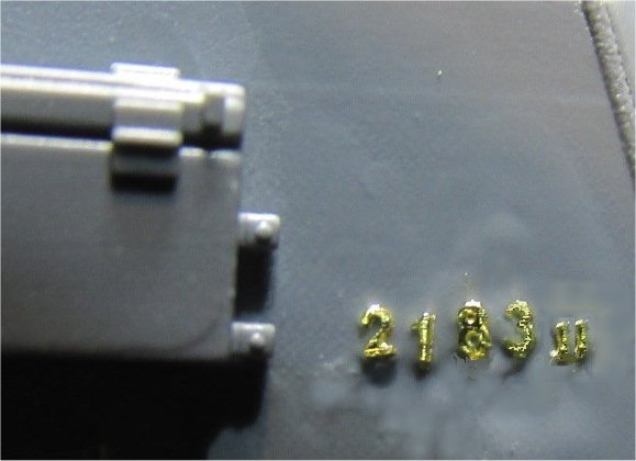
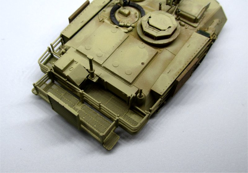
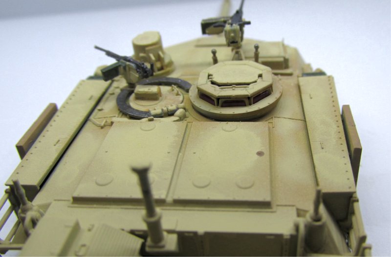
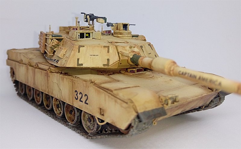
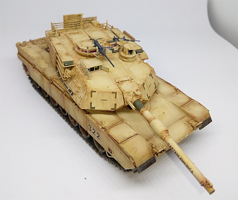
III: Turret This is where the most part of the assembling work takes place: steps 3,4,5 and 6 of the manual. It is also the part where the kit blows away any competitor on the basis of detail and finesse of the parts, which means an additional extra care is needed. Step 3 is dedicated to the build of the commander's cupola, which is a jewel in itself, with the possibility of having a closed or open hatch and the inclusion of a slide molded .50 cal which comes pre-drilled; as with the driver's hatch, there is a clear plastic part with visors to be inserted (M-1), which should be pre-painted as the previous one. Then, the main gun (slide molded too). Then, the gunner's main sight (pieces J2-5), with a clear plastic insert (M-3), which should be painted black inside leaving the outside clear (not red as the instructions tell you). Then, the GPS/LOS (piece N-11), to which you will be adding the external lids later, provided as 2 PE parts needing to be folded, assembled either in open or closed position. The clear part of the GPS/LOS (M-2) should be painted as suggested in this interesting discussion on Armorama, again not red as the instructions tell you. Finally, build and add the smoke grenade launchers (sub-assemblies 4 and 5) with boxes (K-2) and tow cables (I would add them finally). Step 4 is rather complex and leads you to build the beautiful, yet extremely delicate, left and right turret storage bins, bustle rack and extended bustle rack. Very fine PE parts are provided for the mesh. Two ammo boxes are correctly provided to be inserted into their place in the lateral stowage bins (K-13), but two jerry cans, which should go on PE-17 and on the controlateral space, are not provided. Three Combat Identification Panels (CIPs) (N-5) must be added in this step: images show that their positioning is rather variable. Step 5 is about the gunner's weapon station and hatch, with another beautiful, slide-molded and pre-drilled 7.62 MG, to be handled with extreme care, particularly when adding the ammo box and the handle; the hatch has a solid plastic handle which can be cut off and substituted with a PE one (PE-3), which will fall prey to the carpet monster almost immediately. Then, attach the whole storage system you have built previously to the turret. Parts O-3, O-4 and L-13 are the AC unit conduit. The antennas (K-12) and wind sensor (K-30) are added too. Step 6 is the final one. Add the external lids to the GPS/LOS (PE-10 and 13), as said previously, plus the PE CIPs to the front of the turret (PE-20 and 21) and a small bracket (PE-25). You think you are finished? No, Flyhawk has one more little nightmare for you: position 4 PE numbers with a final "u" to be chosen among an entire set of numbers to the front left and right side of the turret (in the instructions, it seems they should be only positioned on the right side). This operation is optional: in fact, the numbers are so tiny that, after a coat of primer and two coats of paint, plus washes etc., they become unreadable; moreover, judging from the pics I could find, they look carved more than in relief.
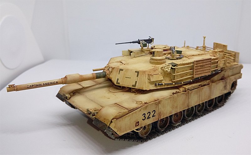
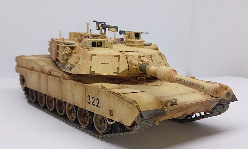
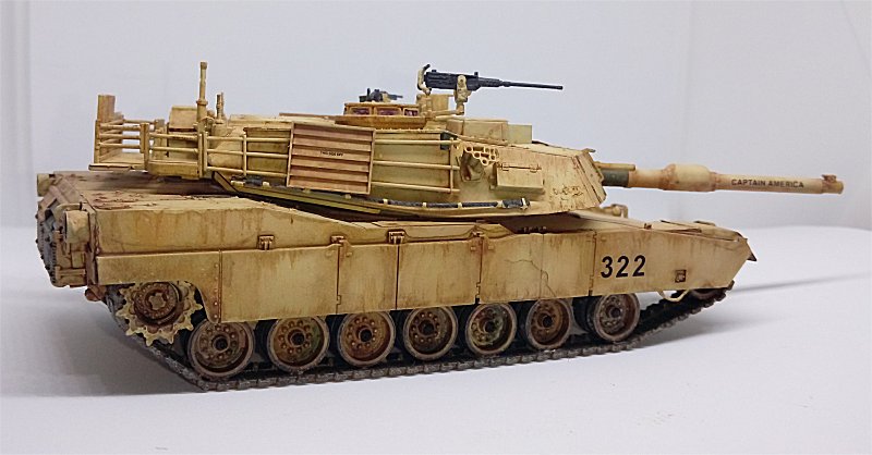
Detailing, painting, markings and weathering All the vehicles for which markings are provided operated in Iraq, so there is no doubt about the base color, which must be overall sand; decals are thin and easily applied; Flyhawk provides 2 PE parts (PE-22 and PE-23) for plates with numbers on extended bustle rack. Tiny decals with "this side off" to be applied on CIPs are provided too. No modern US vehicle is credible witout lots of extra stowage, like tarpaulins, sacks, boxes, spare wheels etc. They can be scratchbuilt, or taken from two excellent sets like the recent T-Model Modern U.S. Military equipment or Legend M1 Abrams Stowage Set. Sadly, this will hide the beautiful storage bins, bustle rack and extended bustle rack. For reviewing purpose, I did not add anything to let those parts be visible. About weathering, many M1 looked rather new indeed, while others looked really dirty, with wheels of an undefined brownish color, with sand paint peeled off from continuous abrasion showing the underlying original green; speaking about wheels, notice that the real hubs are made in transparent plastic to check the level of lubricant, so they should be painted gloss black. Tracks should be treated with pigments to cover the lack of detail.
| ||
Conclusions Flyhawk bounces between WW1, WW2 and modern era, always giving continuity to the excellent quality of their production which is becoming sort of gold standard. Their bet on producing yet another Abrams in 1/72 is largely won, because theirs is without doubt the best one, with details not present even in 1/35th scale (for example, not every models of the Abrams in 1/35 have PE parts for the rear engine deck screens). This said, the conclusions are easily drawn. For me, I am eagerly awaiting for next Flyhawk kit (where will they lead us ?). |
||
| Review sample provided by Flyhawk |
Back to Flyhawk Kit List |
Back to Construction Review Page |
Article Last Updated: 21 August 2017 |
Back to Home Page |