|
Nowadays
only UM and Extratech have the M10 in their catalogue. A further quick
building model is provided by Armourfast.
Despite
this, every batch and variant can be made with dedicated boxes for
the early or mid production batches. The later production batch can
be depicted using the modified turret present in the 17pdr armed British
Achilles, depicted with specific kits by the three firms or in the
UM M10A1 kit.
I wanted to make a vehicle of the mid production batch (which saw
widespread use in Normandy as well as in Italy and the Pacific) so
I bought the UM kit no. 202 |
| The
UM kit is composed of seven pine green plastic moulds and a PE set.
Two moulds are doubled, saving time and work for the cast makers.
There are a lot of little parts, some unused, like the early production
counterweight (a bit thin anyway) or the 17pdr gun and mantlet. Mostly
they are quite well made. The bigger parts often suffer of sink marks
which need to be filled. In such cases I use cyanoacrylate glue: it
is quick drying and fills the smallest holes very well. It is clear
and its use is therefore not very well visible in the photos (sometimes
this is impossible since it looks like the plastic itself). Other
parts requires some work being not well made or well detailed and
will need a good photographic reference. A dry fit test is highly
recommended before gluing.
Basic dimensions are correct according the sources consulted. The
turret type correctly depicts the early/mid production batches with
the sloped upper rear. The counterweights are correct; however the
early production smaller counterweights are present in the kit as
spare parts (I suppose the early production kit contains the same
moulds with a different decal sets). Such early vehicles fought in
North Africa and in Italy; however some old M10 made it to Germany
after the southern France Dragoon landing. The later production used
bigger counterweights joined to the late turret which had vertical
rear upper plates.
The welded attachment points (for the hull and turret) are separate
pieces, giving UM the possibility to use the same mould for the M36
(which could have them or not). Appling them is an additional work,
I know, but I appreciate it because if they are already moulded in
place, they could have a wrong appearance. An area poorly depicted
is the rear plate, missing the exhaust and not well refined.
One thing not always remarked is that differing from the Sherman tank
variants used by the US Army, the Fisher built M10 had a diesel engine
(this plant produced the M4A2 too) while the Ford built M10A1 (kept
in the stateside for training) was based on the M4A3.
A deep wading trunk would be welcome, being not included (it was different
from the types used by the various Sherman tank variants).
The top cover for the turret, made in the winter 1945 as a field modification
in the NWE by the 536th Ordnance HM Company, understandably is not
proposed as an alternative part.
The decal set, as in other UM kit, is a bit poor and having only lend-lease
vehicle, is useless to make my US Army vehicle.
Having said this, to make my mid production M10 tank destroyer, I
had to perform some basic corrections. It is a typical Normandy vehicle,
but is correct for both the Italian or German front. As already noted,
good photographic sources are needed to detail the neglected parts.
I used Hunnicut’s M4 book and Zaloga’s “US tank
destroyer of WW2”. Other useful photos were found here.
|
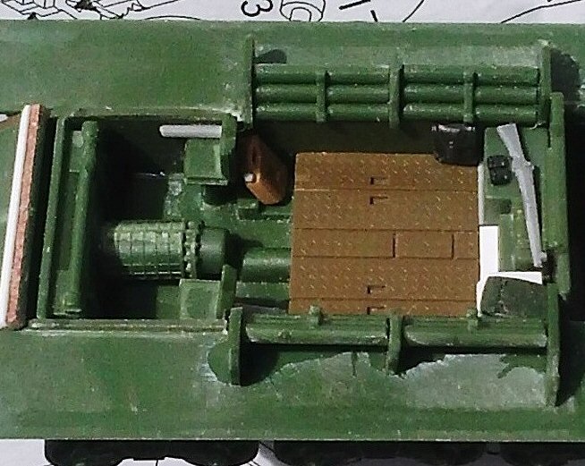
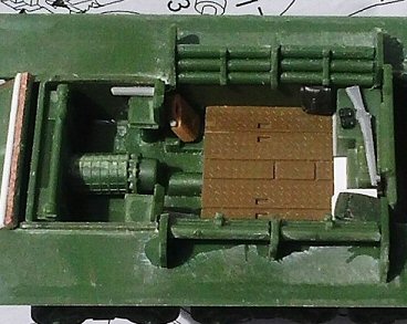
Hull
Interior
•
The floor being smooth, I replaced it with a spare from an Italeri
M4A1 which has the anti skid finish.
• The triangular box at the left was trimmed, otherwise the
floor panel opening would be blocked.
• The ammo racks 9E are depicted only in their central position,
the first and the third are missing, so I had to make four new pieces
with plastic.
• The fibre ammo containers weren’t vertically placed
but sloped. An easy fixing.
• The piece 26D is a box that can be used or not.
• I didn’t detail anymore parts that aren’t visible
through the turret. Instead I put some personal items (a rifle,
backpacks or ammo) to add a bit of life to the model in the visible
areas.
• As far as I’ve found, while the turret interiors and
the internal surface of the hatches were olive drab, the hull interiors
were white with the exception of the olive drab floor (because it
is visible from above) or white overall. I choose the OD/white colouring
because I think it's more appropriate for an operational vehicle.
|
 |
|
|
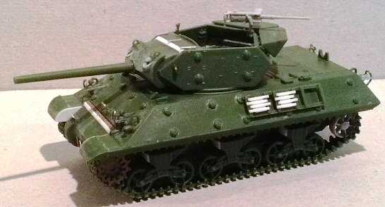
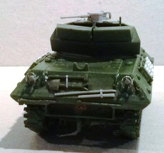
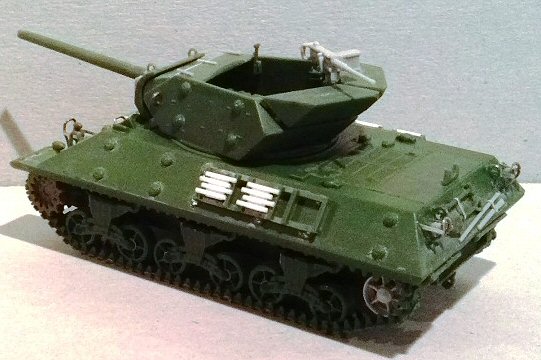
Hull
Exterior
• The transmission cover is wrong. The sides bulging looked too
narrow and gave me a strange impression. I didn’t find a technical
drawing of the part; anyway comparing it with a M4 tank cover I confirmed
my first impression. To solve the problem I had to replace or correct
it. I successfully tried the second way: I glued two pieces of 1 mm
thickness plastic on the sides. Once dry, I trimmed them to the external
cover profile then I cut the cover in the middle, removing 2 mm of plastic
from the centre. Then I glued the two halves using the sides as referring
points for the right alignment. After filing and sanding it, I glued
the bolted PE stripe and then a 0.5 x 1 mm plastic stripe. This was
worked to depict the cast-in bolt heads bullet guard. At the end I erased
the plastic excess to restore the interlocks with the sides and glued
it in place. The M10 early differential covers were usually of a more
rounded and “fatty” type than those of the Sherman tanks.
See a good photo before making one (you’ll need some putty…).
• The M10 was powered by a diesel engine like the M4A2. I had
to replace the belly plates (right for a M4 or a M4A1) with the ones
carefully scrapped and thinned, from an Italeri M4A1 (which has them
incorrectly).
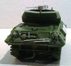
• The rear plate misses the exhausts. Being based on a diesel
engine, I took the exhaust from an Italeri M4A2 that was converted to
a M4 and I used them after being made round according on the sources
consulted. Their scratch building is quite easy anyway, being made with
rounded pipes.
• The instruction don’t show them, anyway I glued the pentagonal
plates (placed in the greyed area at the right of the bogie number 7
on the moulds A) at the sides of the rear plate 33D.
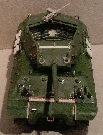
• The deflector needed to be carefully cleaned of the ejector
pins present in the inner surface, I opened the upper side (from which
the engine air come) then I sanded it externally to make the side shape
more rounded and in the centre I opened the hole which leaves the exhaust
smokes flux free to go through. When glued in place it wasn’t
placed vertically, but a little sloped.
• The upper rear plate (10C) had a notch similar to the M4 tank;
it was made with a file and a sharp knife.
• I replaced the PE vertical sides of the fenders with thin plastic
ones because they looked better in my opinion.
• A good photographic source was used to positioning the welded
attachment points (pieces 20E) which don’t have marks to refer
to. A careful job is needed to cut them off, to trim them, to place
them and to avoid losing some of them.
• The rear lights are undersized, I made new ones with plastic
rod segments rounded on one side.
• The PE brush guards included in the kit are too much fragile
for me. I scratch built new brush guards so I don’t know if they
are correct after being folded.
• The tools need to be carefully cut off from their sprue; they
easily can be broken or bent. Check the photo of your subject for the
exact placing (you will note the shovel handle is one millimetre too
long). If your subject depicts a 804th TD Battalion in Italy, their
placement was field modified, being placed on the hull sides in four
frames (you will need three further tool sets). Glue the pick after
having positioned the rear right brush guard.
• The horn 30B received a support and was positioned on the glacis
in a more common place for the M10 seen in NWE.
• The grouser holders (a delicate part to cut off from the sprue)
can be placed freely along the hull sides. Some vehicle had them forward
or backward the classic position suggested. Sometimes they weren’t
used at all. When used the bolts were along the horizontal stripes,
so the vertical ones must be positioned just before or just after the
bolt heads of the welded attachment points. The grousers aren’t
depicted and I had to reproduce them with plastic rods segments (they
weren’t exactly rounded, but these are better than nothing). Sometimes
the grousers were carried vertically along the whole rack.
• My M10 received a quite common optional: a step welded on the
transmission cover, joined with another one the right side of the cover
itself. In such cases a handle was often welded between the lower central
glacis attachment points so I added it too.
|
|
|
  |
|
Turret
• The turret-hull interlocking system is weak. I made a new
one using two plastic pieces and a cut in the hull ring.
• The plate over the gun mount is wrong: it goes straight
against the roof (piece 3D). I cut the upper sides of the mount
with a thin blade (the shaving ones are perfect) and the upper part
of the mount was folded downwards to reach the correct position,
under the roof. When I added it, the gap was filled with a triangular
plastic rod that joined the surfaces with a sloped passage. The
final effect must reproduce a bent plate rather than two plates
joined.
• The mantlet sink mark filling job erased the two “U”
reliefs which I had to make new. Also the gunsight hole was closed
and made in a more correct position; its cap was made new.
• Each rear plates have internally a sink mark that needed
to be filled. Due to its position, I didn’t find any better
solution than to make new thin plastic plates glued over them. To
fill the slots I used two layers of vinyl white glue diluted with
water and applied with a thin brush. When dried it seems like a
welding seam.
• The roof received the three bars used to keep the rain guard
tent open, missing in the kit.
• A good photographic source was used to positioning the welded
attachment points (pieces 20E) and to check the interior details
positioning.
• I replaced the .50 with a Trumpeter M4 one, which looks
better to me, detailed in the handles/trigger area and with an added
support.
|
|
|
Wheels
and tracks
• The bogies are well done and need only a little rectangular
thin plastic piece on the forward side. My box had the revised wheels
moulding and I used the open "five spokes" wheels which
are quite well done and with the centred holes, nothing to compare
with the former old mouldings. Inner detail missing apart, the only
thing I had to do was enlarging the holes that are a bit too narrow
for the pins. The stamped wheels are too shallow and I found them
not useful.
• The kit provides only idlers of the stamped type. Also they
are too much shallow and I replaced them with Trumpeter spare idlers.
• The sprockets have a moulding sink at the centre and are too
shallow. I replaced them with Italeri spare ones, they miss a tooth
but this is a typical case where they are partially hidden and the
thing is not visible.
• The track blocks look too narrow when compared with the T74
type, but they looks more right when compared with the T54E1 type,
with little details missing. Get a look here.
I used them with no further detailing however by sanding the outer
side of the blocks and gluing a thin plastic rectangle we can have
a T51 track set.
|
 |
Decals
The decal set give us markings for three tank destroyers. One is a
British vehicle belonging to the 93rd AT Regt in Italy (not in my
sources). The two others are from the free French forces. A good info
source on the net (with photos of both) is: http://www.chars-francais.net.
Here, with the photos for both, you will note that Demon was from
the 7e RCA, 4e Escadron (3e Division d’Infanterie Algerienne),
while Siroco was from the RBFM 4e Escadron (2e Division Blindée).
For my Normandy US Army M10 I’ll use spare bumper codes.
Conclusion
It is a quite well made kit apart from the only areas I found that
were really disappointing: the transmission cover and the rear. Having
said this, the parts I’d preferred different are the tracks:
I think a T48, a more common type, would have been better. Anyway
comparing to the Extratech M10 (well done but of a rare type used
by the British) the UM kit is still a good choice for a US Army vehicle.
|