|
UM Military Technics
|
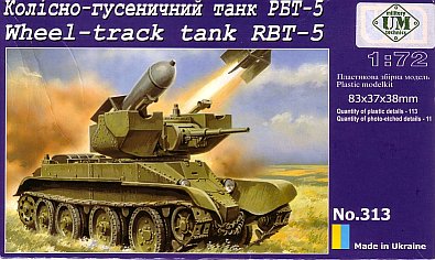
RBT-5 |
|||
| Kit # 313 |
Review by
- Al Magnus
|
|||
|
UM Military Technics
|
RBT-5 |
|||
| Kit # 313 |
Review by
- Al Magnus
|
|||
 |
|
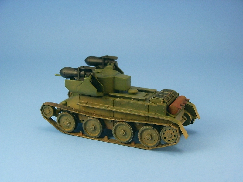
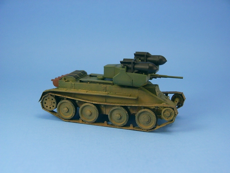
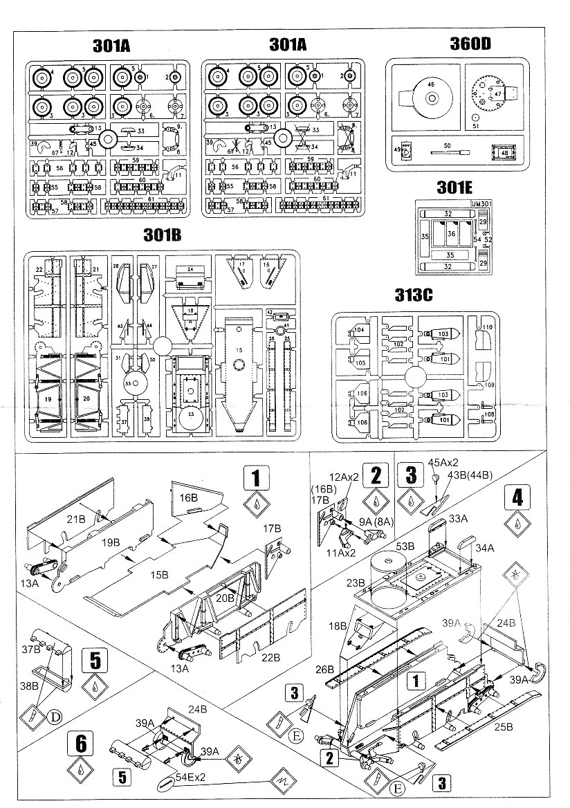
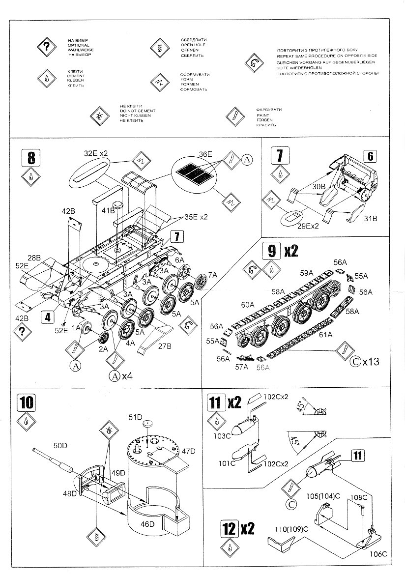
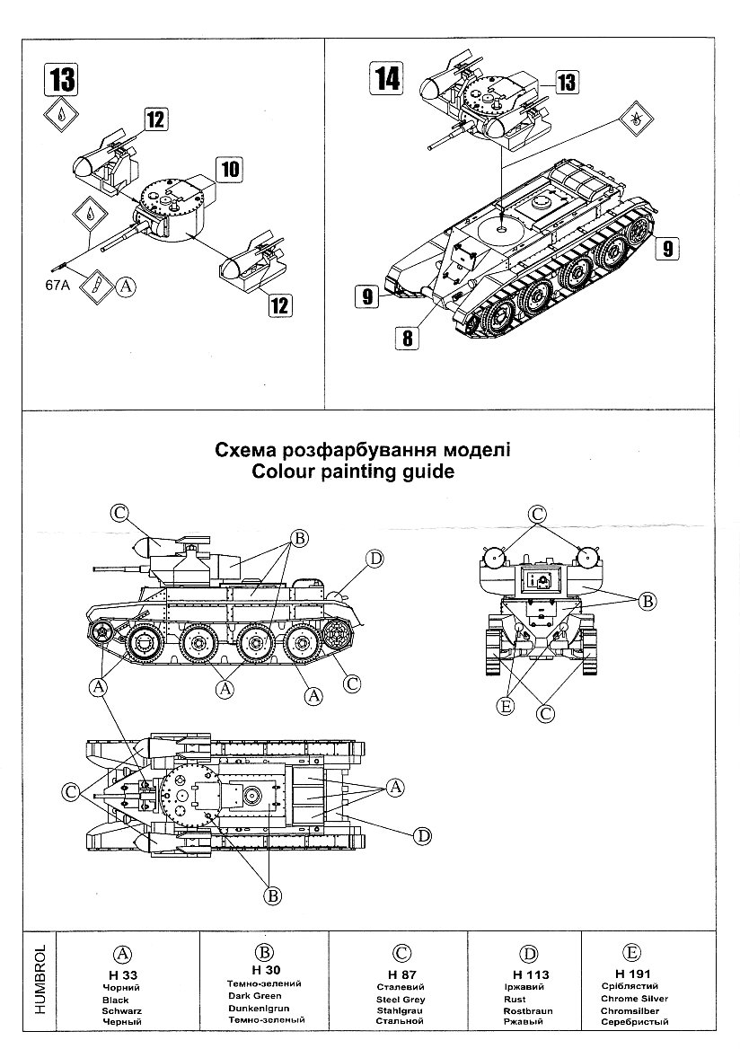
I'm normally a wheeled military vehicle builder, but for this kit I decided to try link and length tracks to see how they work. I considered a few other options but settled on this kit for a couple of reasons - the link and length tracks looked to be fairly easy to build from examination of the sprue shots I found, and it carried rockets which are also an interest of mine. The kit comes molded in a softish green plastic. Casting quality is quite nice with very few seam lines and no flash. There is an instruction sheet, a set of what appears to be generic markings on a decal sheet and a fret of photo-etched parts. There are no locating pins for any of the parts which made for a difficult time in aligning. No pioneer tools are included, though I'm not sure how often they were carried so their absence may not be an issue per se. Fit was acceptable for the majority but I still had to fiddle with some areas to get a good fit. For example the meeting point where the parts for the sides, bottom and glacis plate (part 18B) all meet needed some sanding and scraping to get a good fit. Since I use methylene chloride (MEC) for gluing I was able to hold the pieces in place with my fingers as they dried since the joins were dry within seconds. The two sidewalls are made up of two pieces each (parts 91B & 21B, and 20B & 22B). There is supposed to be a small edge for the hull top to slot into but this was not the case and I had to cut approximately 1mm off the edge to allow the top hull part (part 53B) to fit between the two side pieces and lay flush. This lack of a slot did not become evident until after I had glued the two sides to the hull bottom (part 15B) so I had to do my cut very carefully after the fact with my razor saw. The mantlet is designed to allow the gun to traverse up and down. This requires the modeller to drill out holes to accept small pegs cast into the side of the mantlet (part 48D). I didn't bother with this and trimmed off the pegs and glued the mantlet in place. As mentioned before, tracks are of the link and length variety. I constructed my tracks in two runs per side - a top run and a bottom run. The track pieces were a bit delicate and I did manage to break one of them during construction. Step 9 shows the construction sequence for the track links. Each of the links has a three or four notch end, with the three notch pieces slotting into the four notch pieces. I test fit the runs I planned on building before actually gluing them together. I found that the instructions were slightly off in their sequence. The long bottom run should have the 3 notch end facing to the front of the tank. The instructions show a four notch end and if you follow the progression of notched ends around the wheels, if you have the four notch end facing forward you will get a four notch to four notch join which doesn't work. I also found that I needed one less link for the track links that wrap around the idler wheel at the front. The fenders were to close to the idler wheel at the front of the tank and prevented the track pieces from going between them. I was forced to remove the fenders which I had already glued in place. The resultant sanding to remove the scars in the plastic also removed the majority of the bolt detail. Another oddity was the turret. The bottom (part 46D) has a small circular disc surrounding the locating peg for the turret and hull. This disc doesn't fit into the tiny hole and leaves the turret sit a bit proud of the hull, leaving a small gap between the hull and the turret that allows light through. I found this rather odd and opened up the hole in the hull so that the turret fit flush to the hull. Why UM did this I have no idea but it just makes for another niggly item that has to be done to make this kit look better. Photo-etched parts are nicely done. It was quite easy to bend the engine cover to shape but I found that it came up a bit short and didn't quite meet the top of the deck so I had to add plastic shims to close the gap. I replaced the rear tow loops with replacements made from wire because the photo-etched tow loops are extremely fragile and a bit on the thin side in my opinion. I left the tracks off during painting. After painting the road wheels and idler were super glued to the kit. To make things easier I did not glue the drive sprockets to the tank. Then the tracks were added, first with the bottom run and then with the top run. While adding the tracks I left the drive sprocket loose to allow me to adjust the runs marginally before I glued the tracks to the wheels. Once the runs were in place I set the drive sprockets by adding super glue to the back side where the wheel went onto its shaft. I performed a few basic modifications. I added braces between the fins of the TT Tank Torpedoes as shown on the box top art work. I drilled out holes in the mantlet and the main gun barrel. The small opening for the periscope, which was molded to the turret top (part 51D), was drilled out as well. I also replaced the grab handle in front of the driver's position with one made from bent wire. The last item was a section of chain between the front tow hooks. All in all this was an interesting build, though at times it was quite frustrating with fit problems encountered with the hull and fender pieces.
Review sample purchased by the author. |
| Back to UM Kit List | Back to Construction Reviews |
Article Last Updated: 19 March 2009 |
Back to Home Page |