|
UM
|
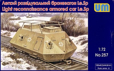
Light Reconnaisance Armored Car le.Sp. |
|||
| Kit #: 257 |
Review by
- Al Magnus
|
|||
|
UM
|
Light Reconnaisance Armored Car le.Sp. |
|||
| Kit #: 257 |
Review by
- Al Magnus
|
|||
 |
|
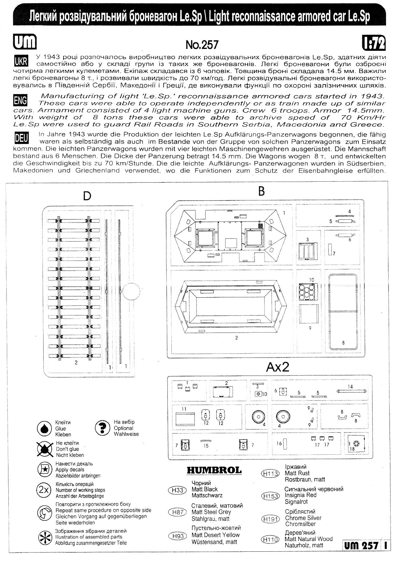
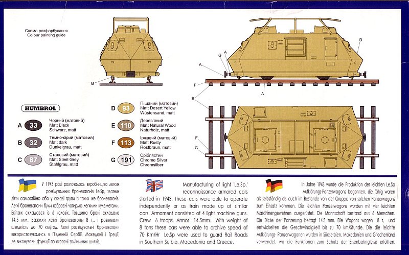
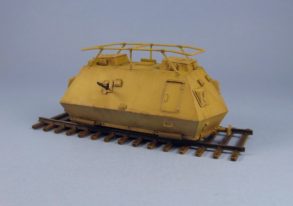
Railroads are one of the primary war time movers of men and materiel for over 100 years. Protecting them is vital if an army wishes to maintain an efficient and secure supply line. In 1943 the Germans started work on two versions of motor driven railcars (aka draisines) for reconnaissance and protection duties - a small lightly armoured version (leichte Schienenpanzer - le.Sp.) and a heavier armoured version (schwere Schienenpanzer - s.SP.). These would be independent vehicles, each with their own motor to allow them to travel singly, hooked together in sub-groups, or as a complete train, allowing operational flexibility and the ability to continue the mission should one of the cars become damaged. Steyr was the designer for both versions. The leichte Schienenpanzer had armour of 14.5mm. The hull had sloped sides, with doors on both sides and covered air intakes on one side. There were two hatches on the roof, one at each end. The vehicle had no fixed weapons. The hull had 6 MG ports - two at each end and one per side. Also included was a bed frame style aerial for radio communications. The light weight gave a top sped of about 70kph with a Steyr 76hp air-cooled engine. Driving stations on both ends of the vehicle allowed it to be driven easily in either direction on the rails. Approximately 40 were built and the first were available in the spring of 1944 for anti-partisan operations in the Balkans, where due to its light weight it could operate on tracks that couldn't support heavier trains. As far as I know, UM is the first manufacturer to offer this vehicle in injected plastic.
Inside the box there are 67 parts spread over 4 sprues, plus an instruction sheet and a small decal sheet of generic German crosses.
Sprue breakdown is as follows:
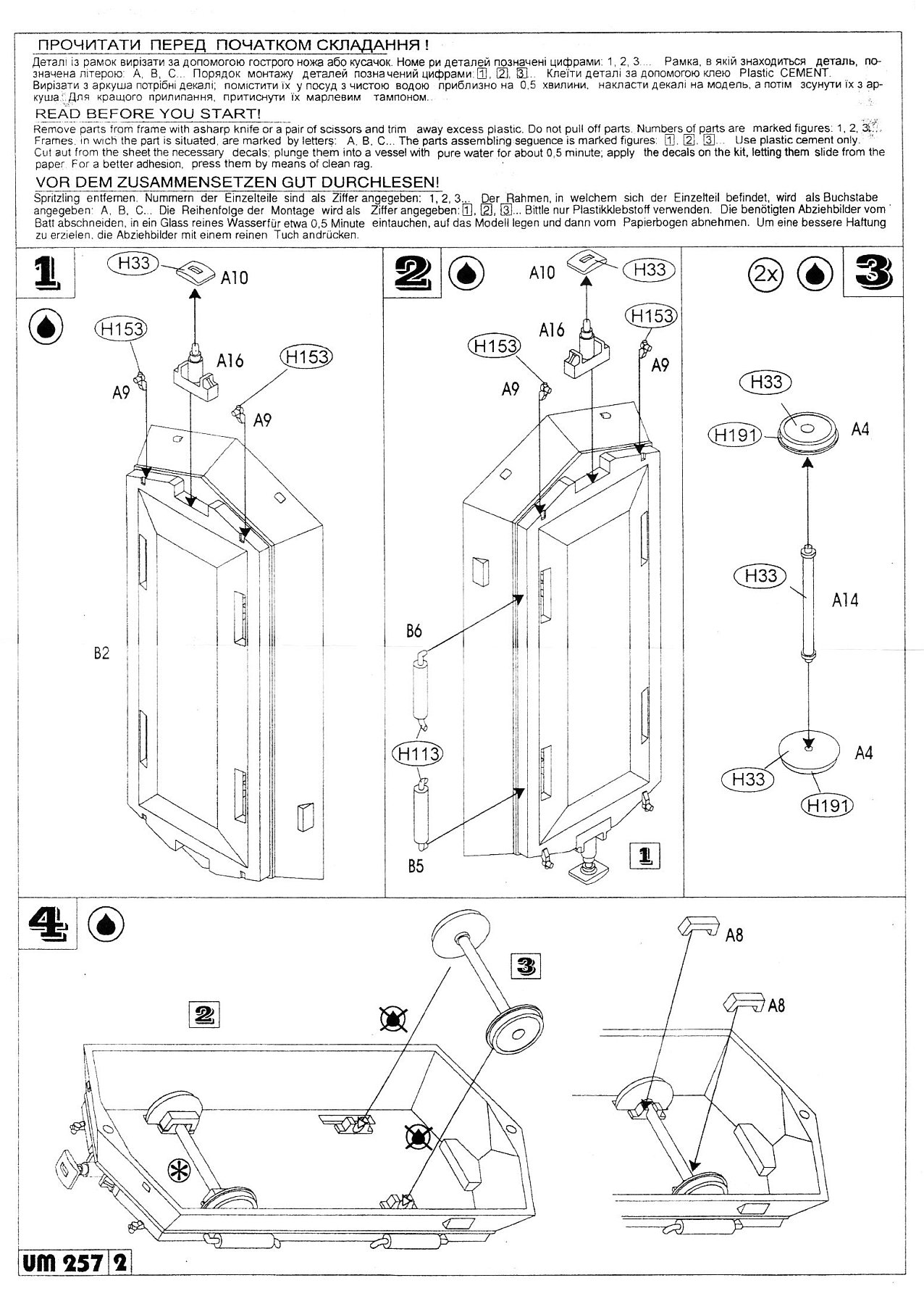
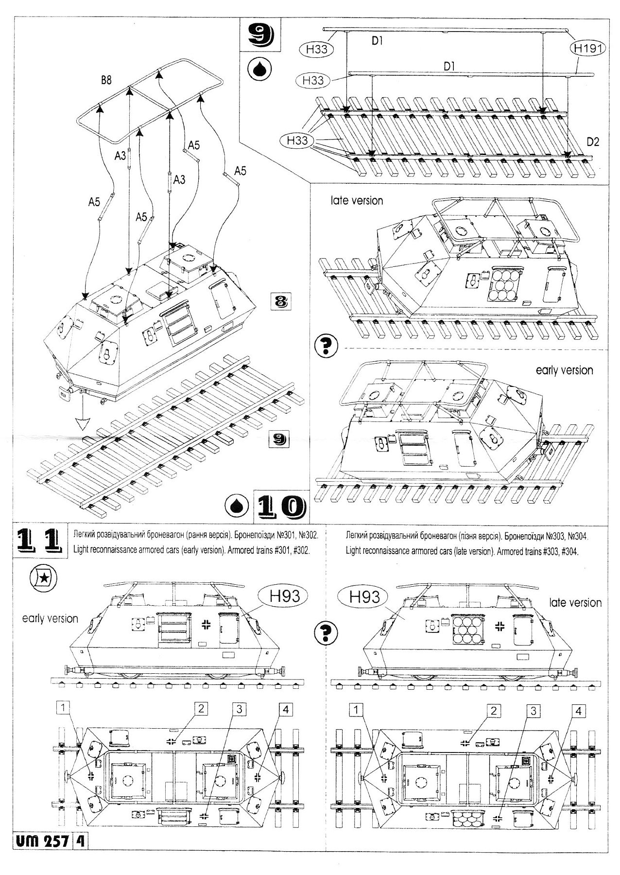
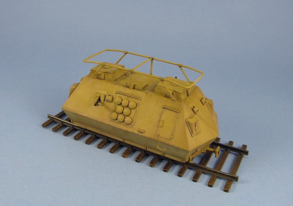
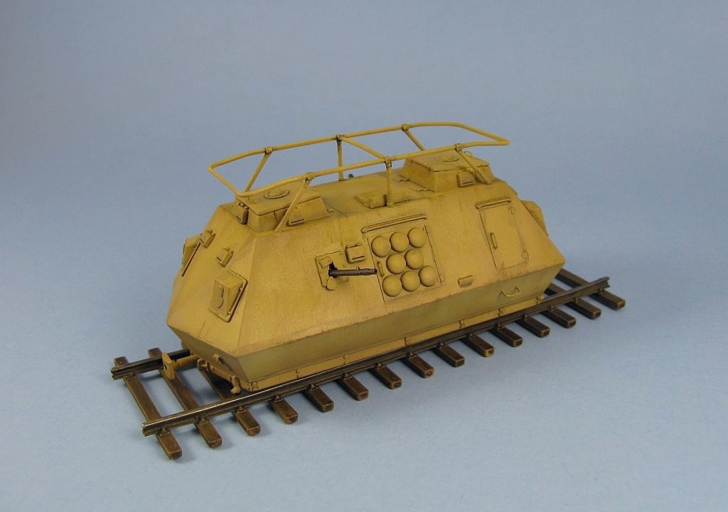
Parts are molded in UM's typical soft, light grey plastic. Flash is minimal and for the most part the molding is well done. There a few spots to look out for where the plastic has some low spots and requires some filling: at both ends of the upper body (part B1) and on the square hatch molded on the hull top (where part B7 attaches to in Step 6). A nice touch is the molding of the upper and lower hulls as one piece units. This removes any chance of alignment problems that you usually get with multi-panel assemblies. For this review, I'll use the instruction sheet as a guide and alter the suggested build sequence to make the construction more sensible. Step 3: Step 9: With some experimentation I found the best approach to the problem was to first glue the wheels to the axles (this is why I suggest the build should start with Step 3) so they can be used as a spacer between the rails to ensure the proper distance between them as they dry. To attach the upper part of the rails to the lower half on the ties, first glue the end points, then glue the remainder of the length between the ends. I strongly suggest using a fast acting liquid glue for this, such as Tenax 7 or methylene chloride (MEK). And be very careful, because until all the parts are attached and set, the rail is quite flimsy and easy to bend or break. After everything has dried, then you trim and sand off the sprue attachment points, and while you're at it add some grain to the featureless wood ties by scraping them with the tip of a hobby knife. There are a couple of oddly placed reliefs on the tracks that siamese with the rails. These should be removed. Step 4: Steps 5, 6, 7 & 8: Parts are provided to build one of two versions, differentiated by the engine covers and gun ports. The early version uses part B3 for the engine cover and parts B12 for the gun ports. The late version uses part B10 for the engine cover and parts A7 for the gun ports. I chose to do the late version primarily because the gun ports were molded better. The early gun ports were marred by prominent sink holes that would be next to impossible to fix without totally destroying the detail. The front and rear gun ports (parts A7) have a small bump on their backside that is intended to slot into a small recess in the hull, but the recess is not present. I had to trim the bumps and sand the bottom of the ports flat in order to mount them to the hull. Doors come as separate pieces (part A2) as opposed to molded directly to the hull as found on the other German draisines offered by UM. Why this was done I have no idea. All the separate door parts accomplished was add more work to the build. They didn't fit flush so sanding was needed to thin them enough to remove a step that would have resulted if they were added as supplied. All of the view ports are problematic. The set that is located beside the gun ports on the lower hull are just a smidge too short lengthwise. The small indent in the hull where they mount is slightly larger than the covers so you have to decide at which end of the cover you want to add your filler. I chose the bottom side because it is straight and I could sand the filler without worrying about removing the molded on hinges. The small ports (part A17) that mount to the sides of the casemates on the top hull are either too large or the casemates are a bit too short. Either way they pretty much span the space between the hatch cover and the top of the hull which isn't what I see in my photo references. Hull vision slots are marked as part A4 in Steps 6 & 7 but they are actually part A1. A4 is the part number for the wheels. At this point I also added some missing detail. The kit has no front and rear headlight covers plus their hinges, so some round covers were punched from a sheet of plastic and hinges were excised from a kit found in the spare parts box. I added most of the missing rivets to the lower apron that runs around the perimeter of the lower hull. The exhaust pipe ends were drilled out. The two gun ports on the left and right side of the hull were opened up and new covers were made to accept a pair of MGs I planned to add later for some visual interest. Foot rungs fashioned from thin wire and added to the lower hull. After all this, the two hull halves were joined. Step 10: Steps 1 & 2: Painting: References:
Review sample purchased by the author. |
| Back to UM Kit List | Back to Construction Reviews |
Article Last Updated: 12 May 2011 |
Back to Home Page |