|
Trumpeter
|
Sd.Kfz.184 Ferdinand |
|||
| Kit #: 07205 |
Review by
- Al Magnus
|
|||
|
Trumpeter
|
Sd.Kfz.184 Ferdinand |
|||
| Kit #: 07205 |
Review by
- Al Magnus
|
|||
 |
|
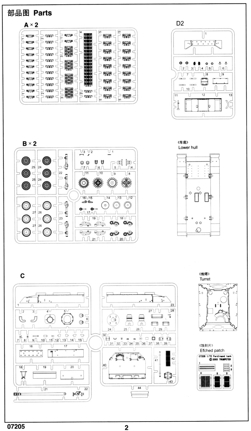
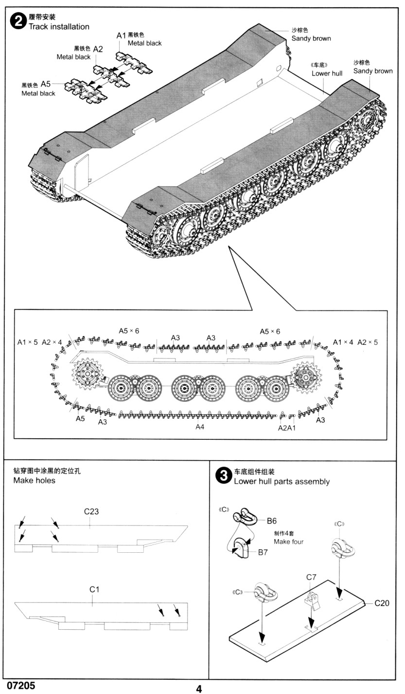
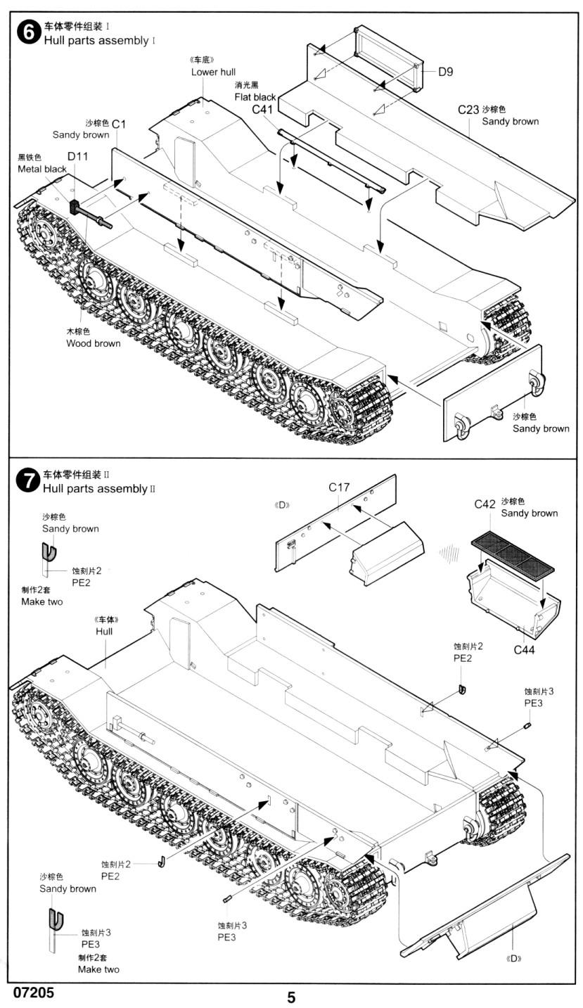
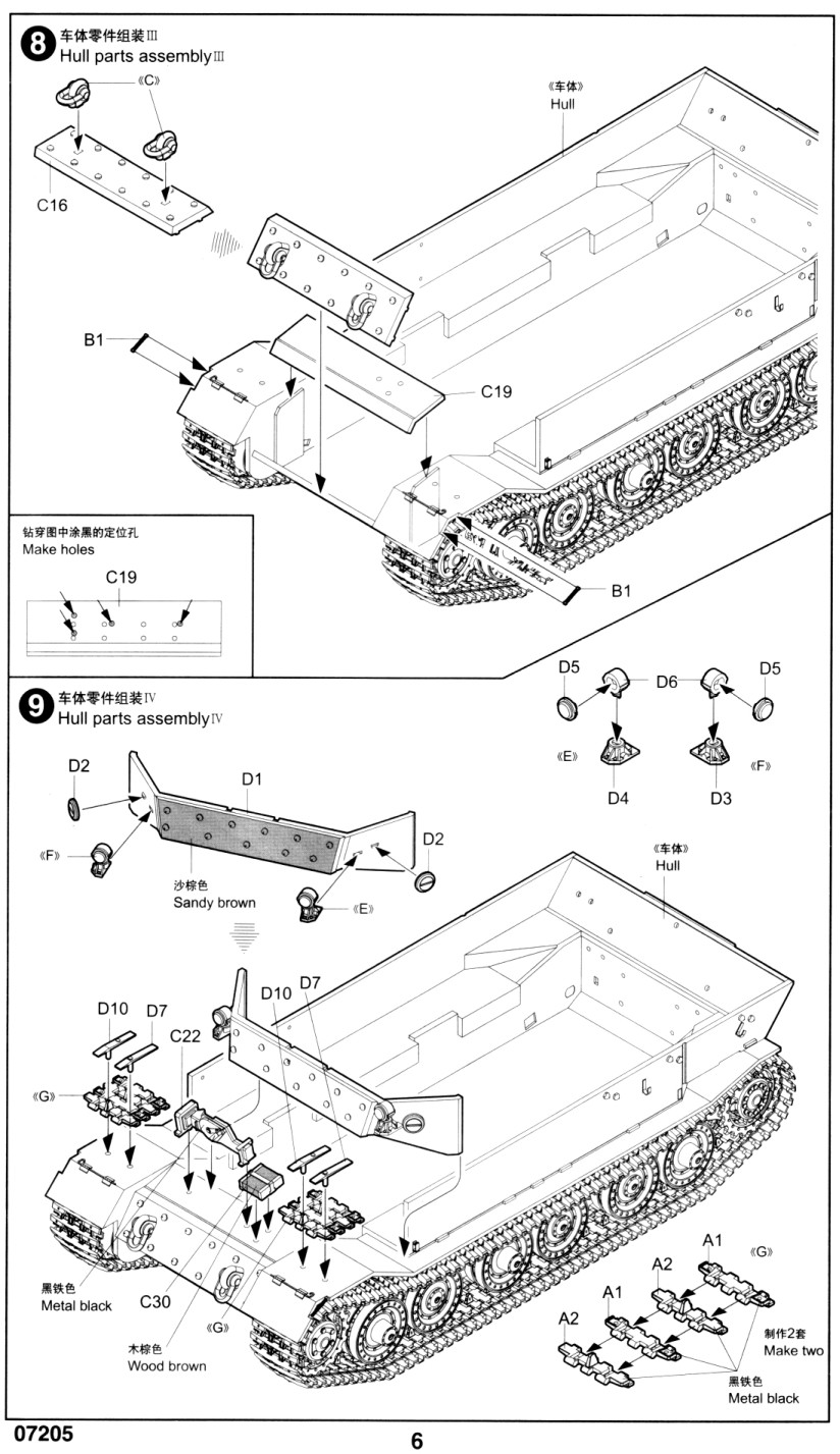
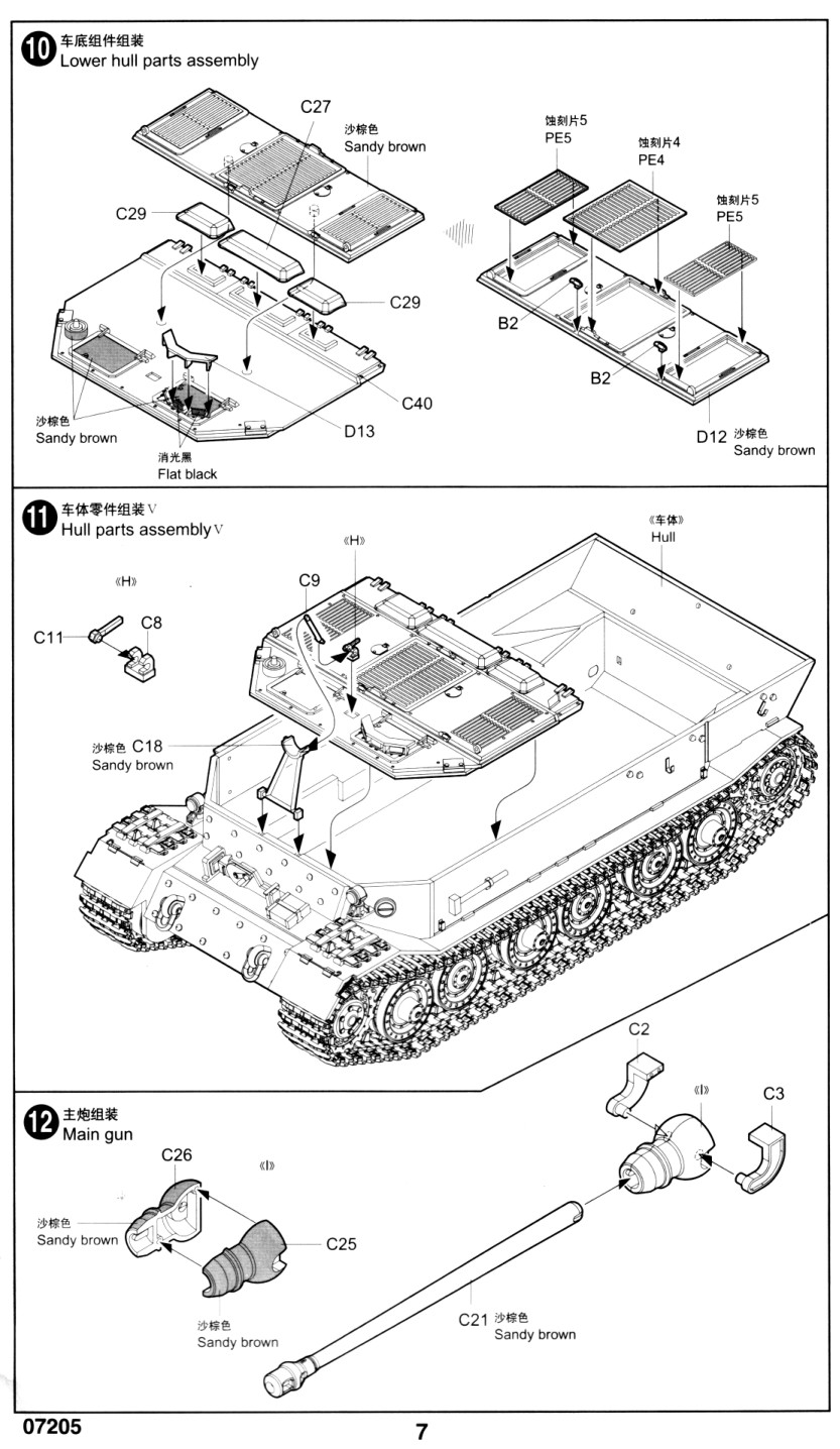
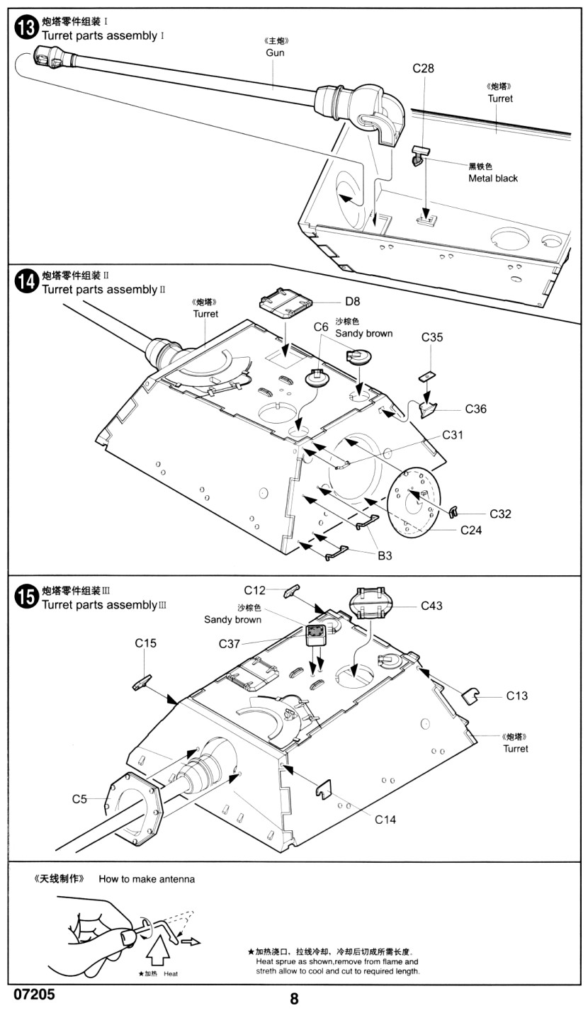
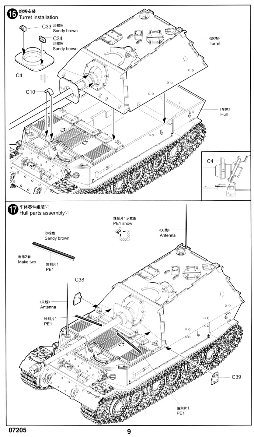
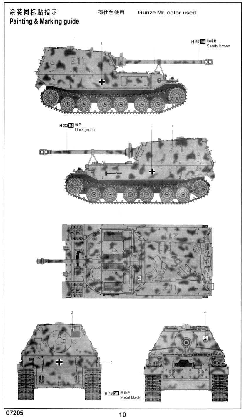
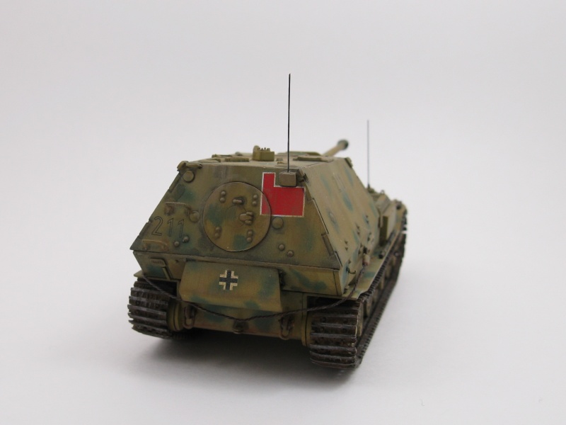
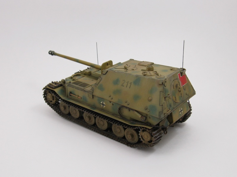
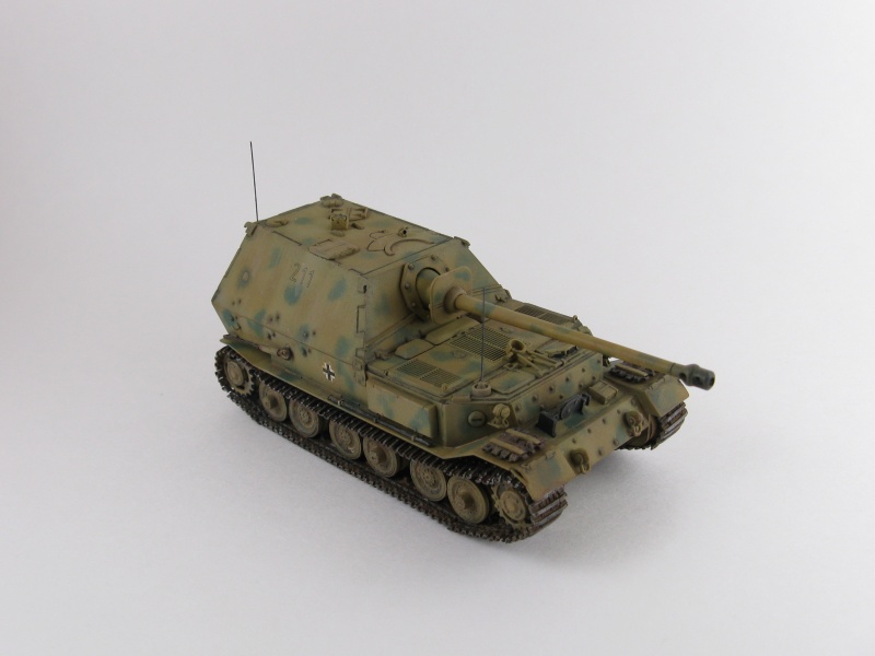
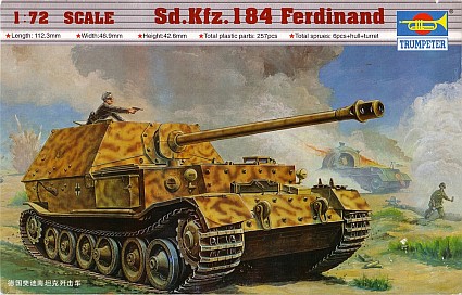
The kit comes spread over 6 sprues, one photo-etched fret and a separate hull and casemate pieces, totaling 254 plastic parts and 9 photo-etched parts overall. The decal sheet offers only one marking option which isn't identified. From what I can gather the markings are for Ferdinand number 211 of the Schwere Panzerjäger Abteilung 653, circa the Kursk battle in 1943. The decal option doesn't match the artwork on the box top. I figure the best way to describe the construction is to present my observations and changes in relation to the steps in the instruction sheet. Step 3: Step 4 (which is shown as a duplicate Step 2 on the instructions): The tracks were built in three runs to lessen the work when the painting the tracks and to make installation following painting easier. Though this did make painting much simpler I discovered that adding the parts afterward made alignment somewhat difficult and I wound up with a vehicle that has a bit of a 'knocked knee' look to the tracks when viewed directly from the front or rear. I think the problem arose with the mounting of the run that I had built around the drive sprockets and idlers. When I added my super glue to the axles and pushed the idlers and sprockets onto the axles they wound up too close to the hull in relation to the bogies resulting in a minute jog in the tracks. The road wheels fit poorly to the axle stubs. Most of the holes on the reverse side of the wheels are too big for the axles, so some care is needed to ensure they are glued on straight. Step 5 (which is shown as a duplicate step 3 on the instructions): Step 7: Step 8: Step 10: Step 11 & 16: Step 16: Step 17: Thread is provided for the tow cable but I found it to be too wispy to use and replaced it with some strands of thin wire twisted together. The cable is not even shown in the parts diagram on the instruction sheet nor is there any instructions as to how and where to place it on the model. I made some covers for the cable ends from some plastic rod, drilled holes in each end, and glued the cable and hooks into the holes. I wanted to route the cable as seen in most Ferdinand photographs but I inadvertently made my cable a tad too short so I improvised and routed it from side to side around the rear of the vehicle. I drilled holes for the antenna mounts and use some guitar wire for the aerials. The instructions say to use heat stretched sprue but I like the look of guitar wire better. The instructions also provide no information on how long the antennae should be so I guessed the length from photos found on the world wide web. The carpet void claimed a few pieces on this kit, which was unusual for me. I lost the door handle (part C32) so I made a replacement from some thin copper wire. I also lost one of the headlight covers (part D5) which forced me to replace them both with a pair found in the spares box. To make painting easier I left the door off and used the hole to insert a handle. Decals were excellent. They snuggled down tight after some dosing with Microsol solvent. All in all this is a nice kit, but the building proved that the great looking moldings in the box had a few issues with fit that make this kit more of a challenge than it first appears to be.
Review sample purchased by the author. |
| Back to Trumpeter Kit List | Back to Construction Reviews |
Article Last Updated: 13 June 2009 |
Back to Home Page |