|
A Little M31 ARV History For The Modeler
The M31 was a conversion of the American M3 Medium tank for use in the recovery of disabled armored vehicles during the Second World War. British recovery vehicles were called
Armored Recovery Vehicles (ARV), the US Army term for the M31 and M32 was Tank Recovery Vehicle (TRV). I will use both terms interchangeably here even though the British Sherman based ARV
was quite different from the American counterparts. While the M3 tank was taken out of front line service in Europe by 1943, the M31 remained in service till the war's end, never being
fully replaced by the M32 TRV, which was based on the M4 Medium tank. The M31 was first issued to the US Army 1st Armored Division (Old Ironsides) in Tunisia during 1943.
The M31 ARV was based on the riveted hull M3 medium tank, which is the subject of this model conversion. The M31B1 was based on the welded hull and diesel engine M3A3. There also was an
M31B2 based on the M3A5 tank, which had a riveted hull and diesel engine. The M31 was armed only with machine guns, the 75mm and the 37mm main guns were removed and replaced by dummy guns.
Out of the M3 Medium tank variants produced, Baldwin Locomotive Works converted 805 to M31 TRVs. The M31 was issued to US Army forces, and I have read that 115 were supplied to the USSR,
and some to UK forces and to the Free French.
I have reference photos of M31 TRVs with the heavy-duty VVSS bogies with trailing idler wheels but I suspect these were post-war upgraded TRVs. The M31 was also modified to be a bridging
tank with a long, pre-assembled treadway bridge on the bow and supported by the crane.
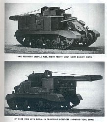
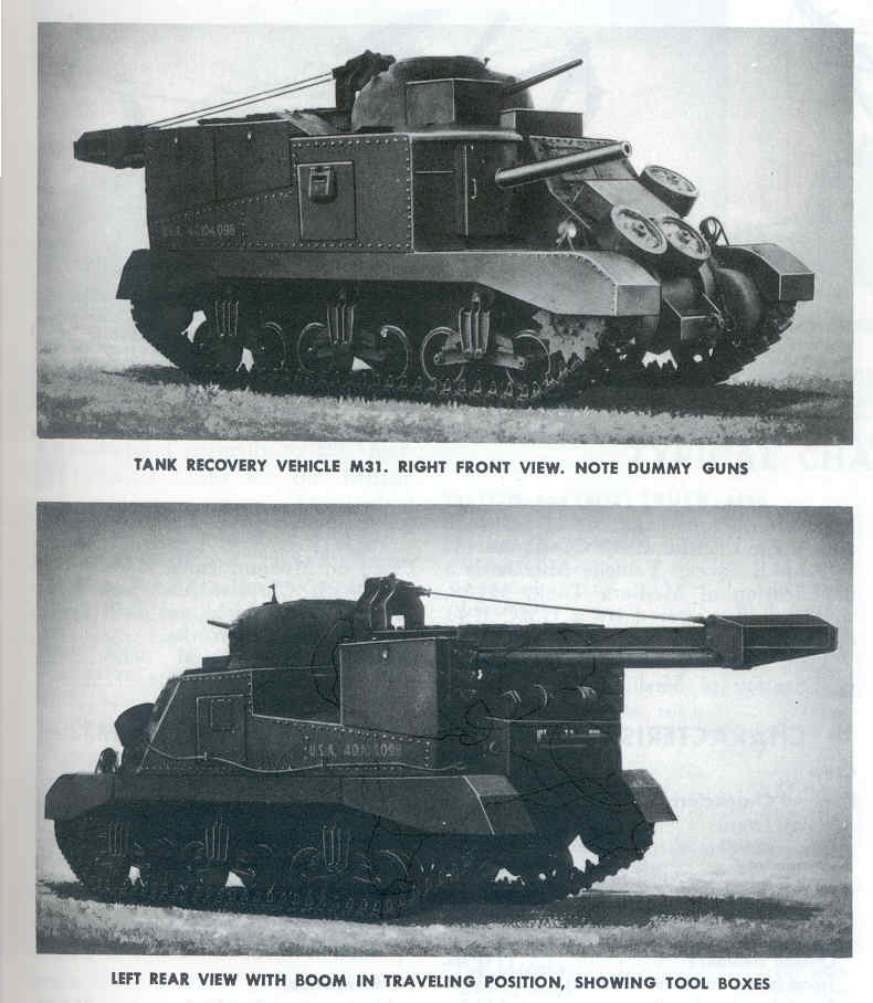
Before we look at the kit, let us study the M31 vehicle to see what we should have. The above two photos are from a US Army technical
book and will help us with assembly.
In the upper photo of the front right we see the original turret but with a dummy gun mounted on the turret rear and a large crane boom mounted where the 37mm gun would have been. The
side hull doors have been replaced by plates with viewports. Some M31s had a solid hull side, with no doors, and just the viewports cut in. The 75mm hull gun and the mount replaced by a door and
dummy gun, a simple pipe. The riveted hull construction is evident. On the glacis is a storage box surrounded by three spare road wheels. Below the spare wheels appears to be a towing
pintle mounted on the 3-piece bolted differential housing. On the starboard-side engine deck are two tall storage boxes.
The suspension has the initial VVSS bogies issued with the M3 Medium tank with the return roller directly over the springs. In wartime photos M31s wore either T41 or T51 rubber-block
track, T48 rubber track block with chevrons, or T54 style steel track. The sprocket wheels here are the plane type though the majority of M31 sprockets I have noted in photos are the fancy
type. The side skirts shown here were typically deleted from US operated M3 tanks in the field but I do have one photo of a US Army M31 in Italy with side skirts present.
In the lower photo we see the boom in the travel position extending out over the engine deck and stern of the vehicle. Unfortunately because of the photo quality we cannot see the rear and
details of the engine doors and air filters. There is only one storage box on this port side. A tow cable is visible running along the lower side of the hull. Unfortunately these photos do not show the cables for the crane well.
The Kit
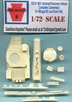 |
I counted 25 amber color, cast resin parts for converting a 1/72 scale M3 Medium Tank kit to an M31 ARV. There are no etched brass or styrene plastic parts and no decal markings, those will
come from Mirage. No cable material for the crane winch is included but I have found that fine string, such as that from a tea bag coated in white glue, works well in replicating small-scale
cable.
This conversion set is intended to be used with the plastic lower hull and suspension from the 1/72 scale Mirage M3 Lee or M3 Grant plastic model kits, though you may be able to use it with
the Hasegawa M3 Medium tank kits with some modifications (see here). This leaves you with an upper M3
hull and turret for another project.
At upper right of the boom is the modified turret with fittings to accept the boom, and two of the three spare road wheels of the solid
spoked type (see instructions Step 2). Below the turret is the V-shaped bracket that mounts atop the boom and will need the center resin cut out so that it looks like an open V (see the
above photo for reference and Step 3 of the kit instructions). Reference photos show the boom is raised via a screw mechanism not included in this conversion set.
The pour plug below the hull mounts pairs of rollers, and brackets that mount on the differential cover, and two trapezoid plates that mount near the end of the crane where the two booms
attach to the crane arm. Right of this pour plug is brace piece shown in the instructions Step 3 that mounts atop the boom end.
The next two pour plugs below hold tubular, telescoping booms, a small roller and the pully that mount on the crane. The two tubular boom sections form an A-frame with the crane that attach
to the underside of the crane when in storage, travel mode. When being used the booms attach to the brackets mounted on the rear engine deck or front differential (transmission) cover.
On the center pour plug at the bottom we have a set of two booms that are store on the rear upper hull plate (see kit instructions photo 8) , a tow pintle missing from the Mirage kit,
that mounts on a tow bracket that mounts on the M31 lower rear plate (Mirage part K02).
|
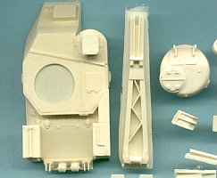 |
In the close up of the kit parts to the left we see the modified M31 upper hull at upper left with the three rear engine-deck storage boxes, bow storage box, and a small storage box atop the former gun
sight location. The edges of some of the boxes have a few air bubbles to fix. The driver's visor on the glacis is to be supplied by the plastic Mirage kit.
Also seen are rollers and brackets on the rear of the engine deck. Right of the hull is the crane boom molded onto a pour plug that will have to be sanded and cut away. The turret at far
right has holes on the front plate where the screw mechanism and cable pass through, these holes can perhaps be drilled deeper during assembly.
Below the turret is the V-shaped bracket that mounts atop the boom and will need the center resin cut out so that it looks like an open V (see the photos for reference).
The hatches are all molded closed, but the resin hull is cast hollow so the doors and hatches could be cut out and replaced by parts from the Mirage or the Hasegawa M3 kit.
|
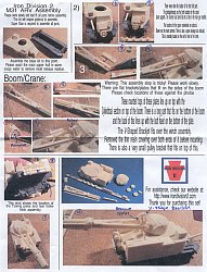 |
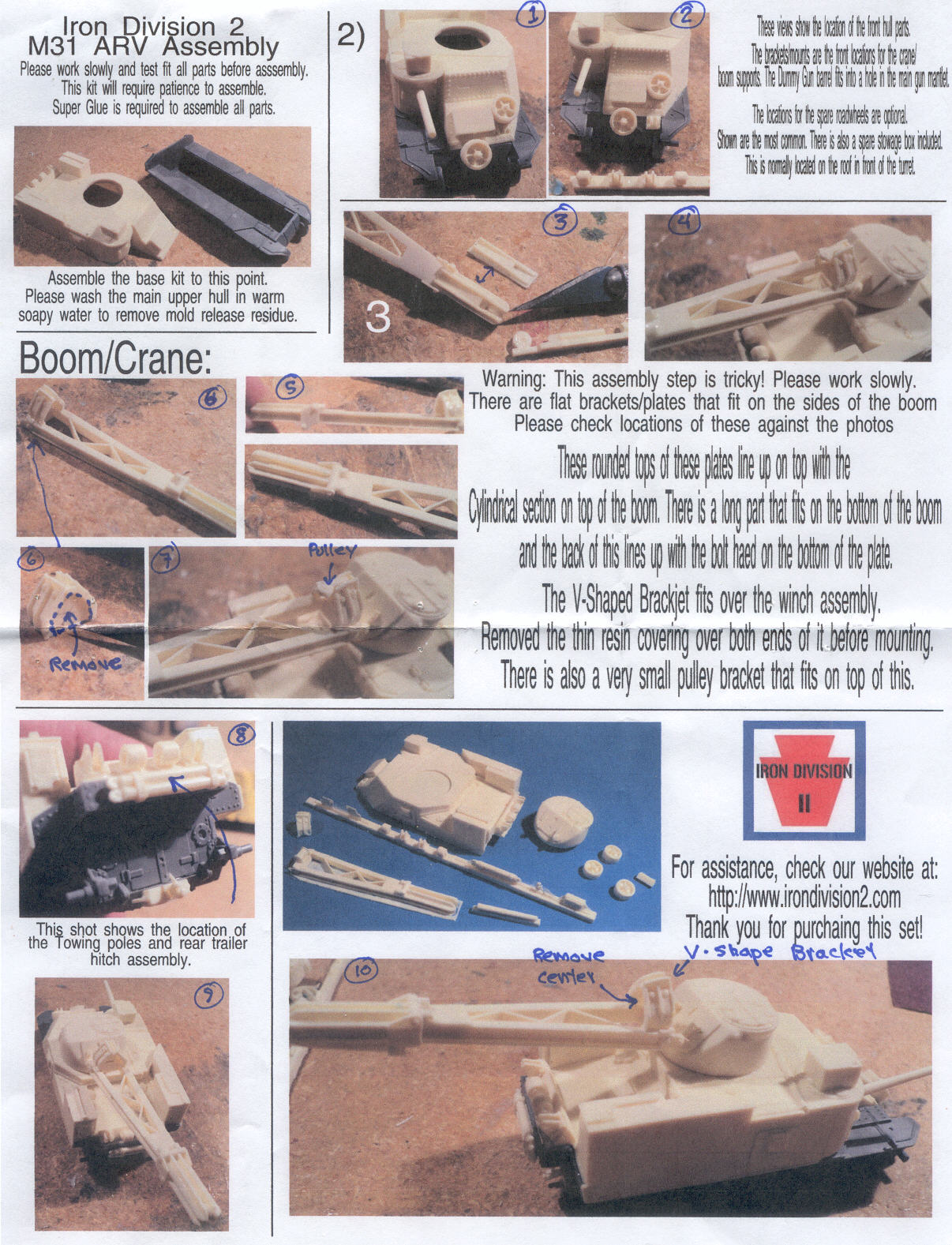
The assembly instructions at left consists of a single page of 11 color photographs with advice in English. Color photocopies seems an expensive approach to me but can work very well. I have
added some personal notations and numbered the photos.
The first three photos, Step 2, show kit parts and the parts to be supplied by the Mirage plastic kit.
Step 3 and Photo 3 shows the bracket plate mounting on the underside of the crane end, with a pulley wheel for the cable.
Photo 5 shows the mounting of trapezoid braces that attach near the end of the crane.
The two photos labeled 6 show the clean-up and mounting of the V-shape bracket at the base of the crane arm.
Photo 7 has the crane attached to the turret with the V-shape bracket and the small pulley bracket that fits on top of the V-bracket.
In Photo 8 we see the towing braces, or poles, mounted on the rear engine plate (part K5) supplied by Mirage. On the resin M31 upper hull are the brackets for the
tubular crane booms and rollers. On the left side storage box is a set of three spare track blocks. On the Mirage lower hull is the new resin towing pintle mounted on Mirage part K02.
Photo 9 and Photo 10 shows a rear view of the assembled parts without the tubular booms assembled and mounted. With studying photos of the crane M31 it appears that the crane acted more
like an A-frame type that would only be used pointed to the very front or the rear of the vehicle. For example, it does not appear to have been used to lift something and then swing it
around by turning the turret such as a ship or a construction crane would do. I am surmising this is why a screw mechanism was adequate to lift the crane. The tubular booms would take
most of the weight being lifted by the cable. |
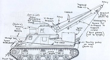
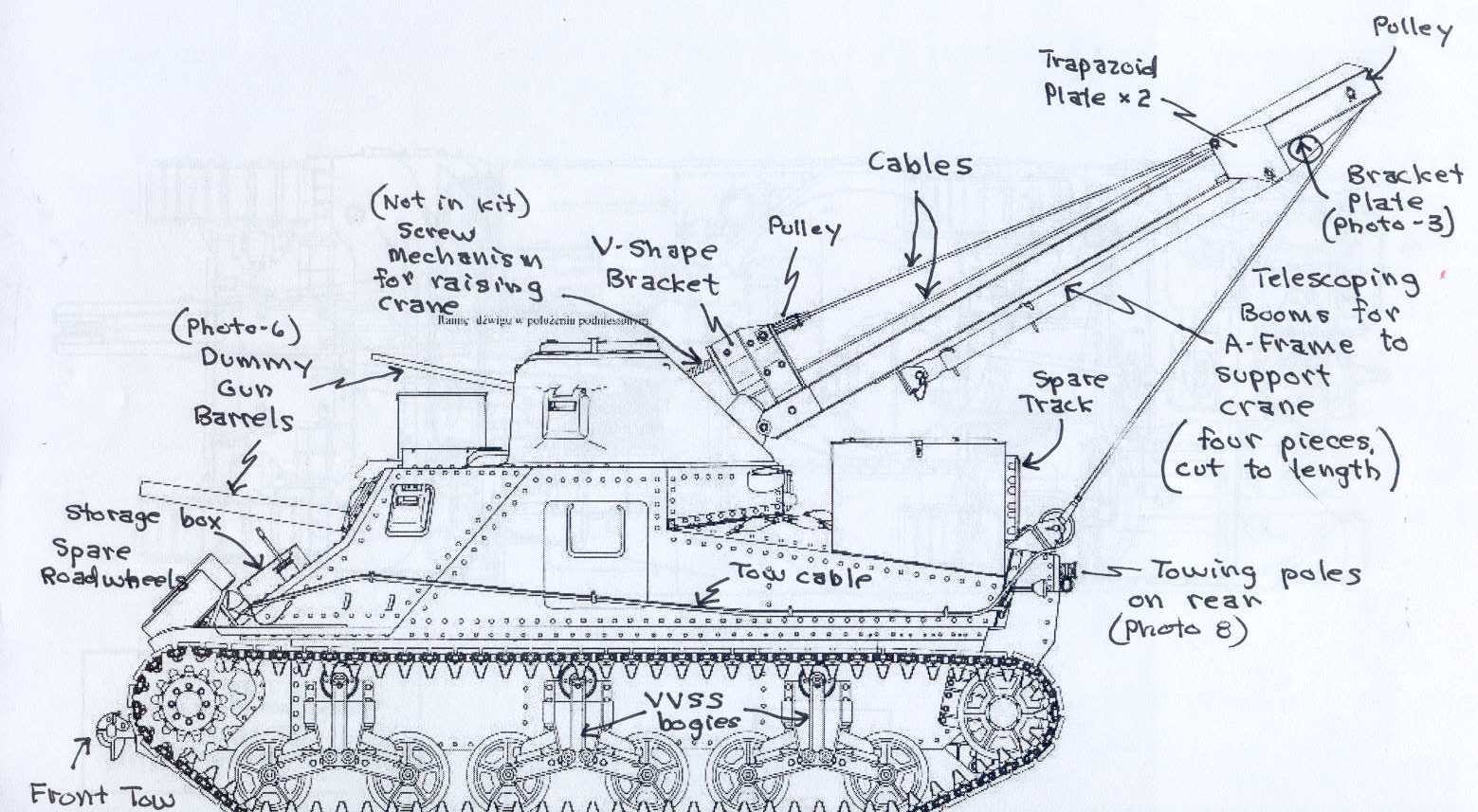
Here is a profile drawing I have labeled to help with identifying and assembling the parts. Please keep in mind that without a vehicle manual I have labeled the parts using the best common
sense terminology I have. This and the photo below will give us some idea on stringing the cables. The cable, front tow pintle and screw mechanism parts are not included in my conversion
kit.
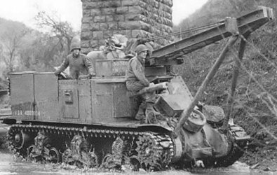
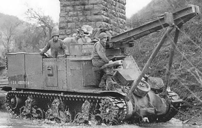
The above photo taken in Italy shows a typical example of the simple markings and monochrome Olive Drab color of M31s. The crane is pointing forward and this is an excellent view of the twin
A-frame boom supporting the crane and affixed to brackets on the 3-piece differential housing. Two steel cables are visible coming from the turret to the end of the crane. Lower on the
differential cover we see the front tow pintle. The track is rubber block with chevron pattern. The suspension consists of early VVSS bogies with 5-spoke open wheels and with a fancy-style
sprocket. One GI is sitting atop the dummy 75mm gun. The other GI is standing in the roof hatch and below is the plated over side door with viewport.
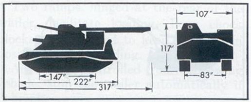
If you wish to check scale of your M31 model here is a good reference to work from.
Conclusions & Recommendations
- I found this to be a very nice resin conversion that is well cast, accurate, and not too complex to build and not too difficult to clean up from the pour plugs. A few small parts such
as the dummy 37mm turret gun and the crane screw-mechanism appear to be missing but will not be difficult to scratch build. The M31 has been on the list of planned kits by Mirage for years
now but I have lost hope of it being actually released.
- Good luck in rigging the lifting cable for the crane, in all my references I have not found any photos that adequately show how the cable is exactly strung though the pulleys and over
the crane.
- Even if you can modify the Hasegawa M3 Medium tank kit to fit this conversion kit, I strongly recommend the significantly better Mirage M3 if you are building a display model.
- This kit can be converted to an M31 for a treadway bridge-laying TRV with the scratch building of a large brace on the nose. It can also be converted to an M33 Prime Mover for the
8-inch gun or 240mm howitzer. M33s also have a cupola ring mounted over the dummy gun position (where the gun sight would be) that appears to be from the Sherman tank turret's split
commander's hatch.
- Some M31s in WW2 photos have 50-calibre machine gun ring mounts on the turret similar to that mounted on US trucks.
References
[1] US Armored Funnies, US Specialized Armored Vehicles in the ETO in World War II, Armor At War Series 7052, by Stephen Zaloga. Concord Publications (2005). ISBN 962-361-085-8.
(This is an excellent softcover book with a description of M31 development and use, eight pages of black and white photos of M31s in service, and four color plates.)
Preview sample provided by Iron Division.
|