|
History
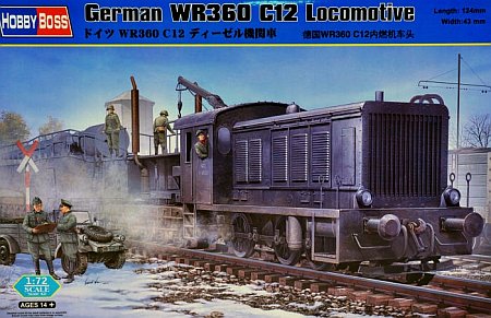
The WR360 series of locomotives were conceived and designed by the German Armed Forces before World War Two. The designation WR360 C12 stood for
Wehrmacht Rangierlokomotive (War Department shunter) of 360hp and the C12 designated a three coupled axle vehicle in the 12 ton range. They
were the pre-production locomotives to the C14 series. First appearing in 1937, the C12 locomotive differed some from the final production C14s by having
only a single speed transmission, limiting it to a maximum top speed of 45km/h, and was marginally shorter in length by 35cm, which I assume may be due to a size
difference between the single versus multi-speed transmissions. From 1939 to 1945 a total of 261 WR360 series locomotive were built, of which 245 were of the C14 version.
I'm not sure exactly where the 35cm difference is found
between the two versions, but from examining photographs of built 1/35 scale renditions of the C12 and C14, it appears that the extra length is seen in the panel between the
front engine access panels and the rear pair of engine access panels.
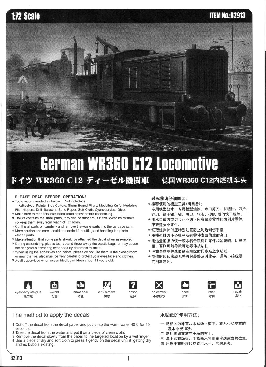
The Kit
I do not understand why did Hobby Boss selected such an obscure subject. My best guess is that Hobby Boss has some sort of association with Trumpeter
and all they needed to do was scale down the Trumpeter WR360 C12 model kit, but it still does not answer why the more numerous C14 version was not kitted by either company.
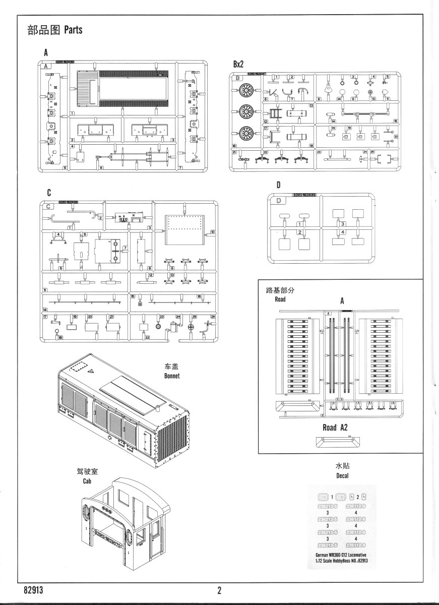
The kit is molded in a light tan hard plastic but for such a new mold it is odd that a lot of the pieces have a seam to remove.
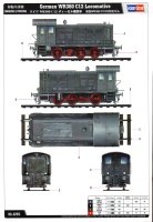
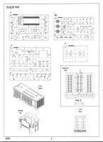
Parts total 139 spread over 6 sprues, with the cabin, engine cover and end caps for the base as separate pieces. Instructions cover 15 steps in exploded diagram
format spread over 12 pages. I found them quite easy to follow. Detail is very nice, especially the one piece cabin and engine cover, but the kit could use some additional
parts as it appears to be a bit simplified in places compared to photographs of the surviving C14 machines. Working on the assumption that the C12 would be much like its
C14 big brother, most of my extra work entailed adding some of this missing detail seen in C14 photographs.
Marking & Colour Options
|
 |
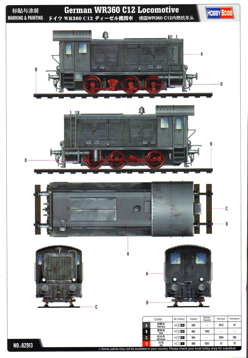
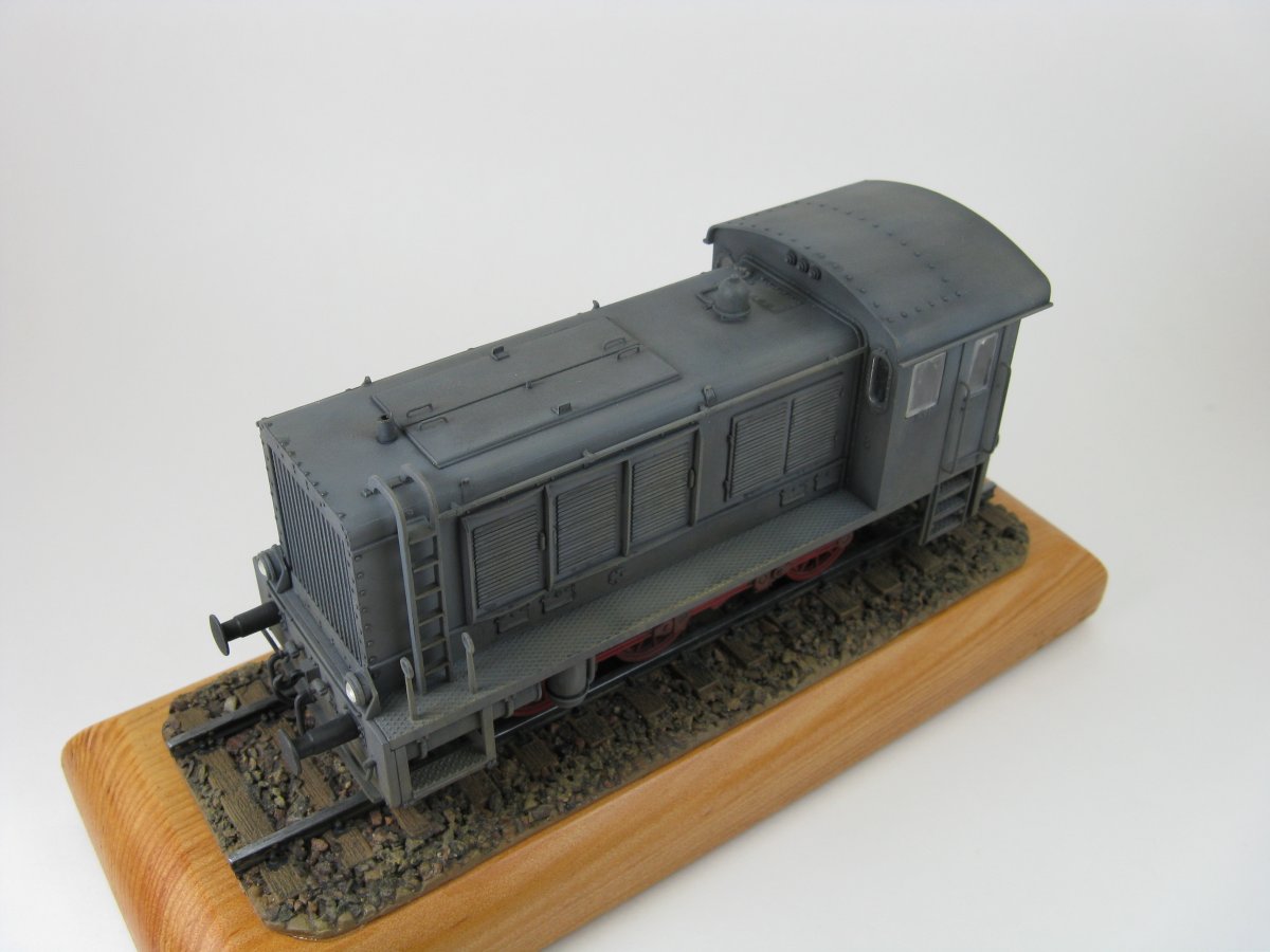
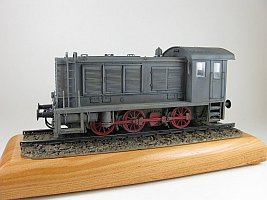
The painting guide is a separate sheet of colour artwork showing one option for an overall Panzer Grey locomotive with red wheels and
connecting rods. |
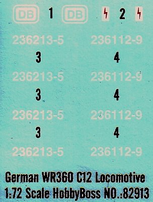 |
Decals are included and have two options, engine numbers 236213-5 and 236112-9.
The decals are a bit of a conundrum. First, the colour guide does mention any of the decal options, and on top of that, the box top artwork shows
a machine numbered V36222, which is not on the decal sheet, and if I'm not mistaken is a number used by the Deutsche Bundesbahn (DB) post-war.
The same can be said for both the red lightning bolt in the small white rectangle and the DB decals which also appear to applicable only for post-war locomotives. |
Construction
After a quick scan through the instructions it seemed the best option was to build the kit as a set of sub-assemblies, with some
intermediate steps for painting, and then putting the sub-assemblies together towards the end. I also noted that most of the parts had locating holes that passed
completely through the part they were to attach to, so wherever I could these were filled after the part was glued in place.
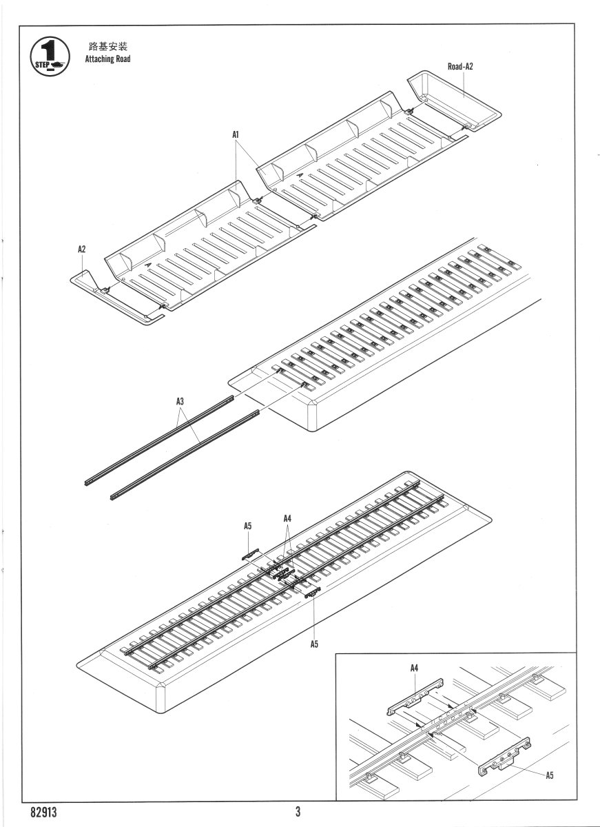
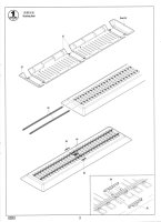
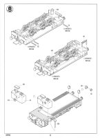
Step 1: Tracks & Base
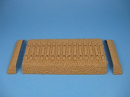
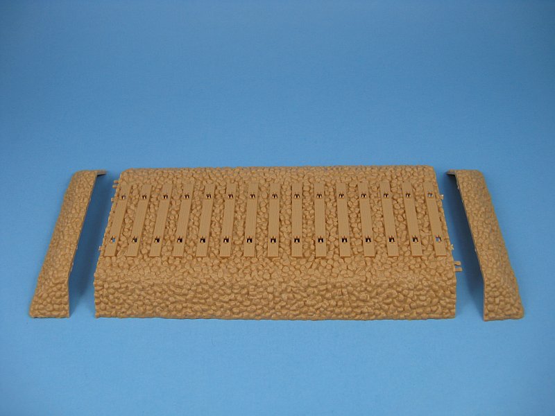
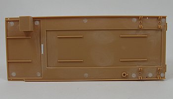
The base consists of two bed sections, two end caps and four rails with accompanying joiners. I am not a big fan of the base as supplied by Hobby Boss.
It looks chunky and the ballast rock is too large, too uniform in size and too rounded in shape for my liking. I discarded both end caps, the connectors, one of the base sections
(the remaining center section is seen above) and two of the rails. I then cut the
the top off the remaining base section, sanded the rough edges and glued on a pair of the rails in preparation to adding it to a wood base. The kit's ballast would
eventually be covered with my own material to break up its uniformity.
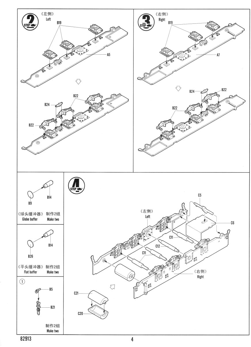
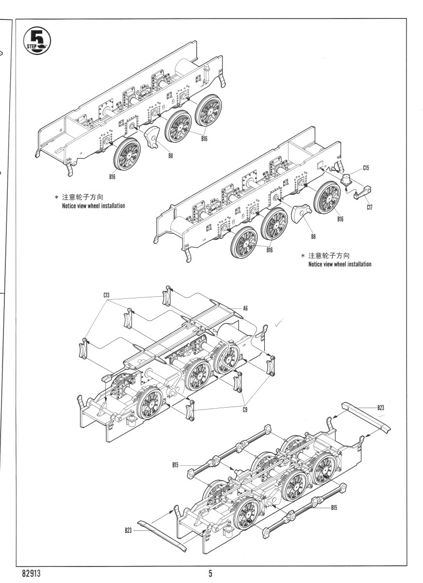
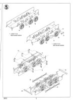
Steps 2 through 8: Undercarriage/Chassis pt.1
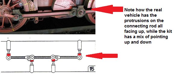
I pretty much followed the instructions as laid out for steps 2 through 4. At Step 5 the wheels, wheel connecting rods and the flywheels were removed from the sprues
to be added later in the build. At this time I noticed what appears to be an error in the kit's connecting rods versus those found on surviving examples of the
WR360 (see picture below).
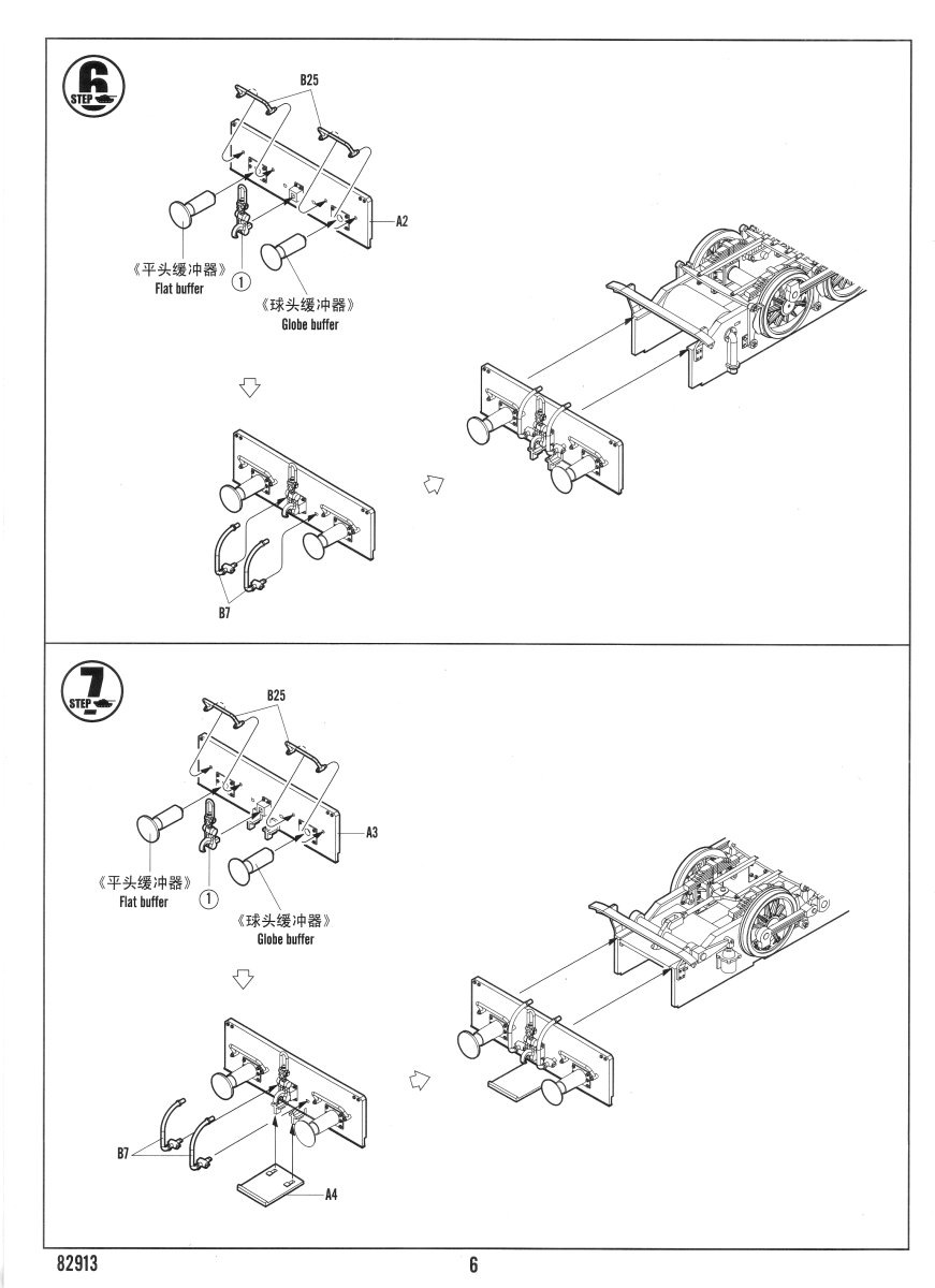
After adding the front & rear deflectors (part B23) to their supports, the small depressions left on their faces were filled.
The small depressions were also filled in Steps 6 & 7 after the addition of the buffers, the rungs (part B25) and the hydraulic lines (part B7).
Adding the hydraulic lines here was a mistake since they are quite delicate and I snapped one off later trying to attach the deck to the undercarriage.
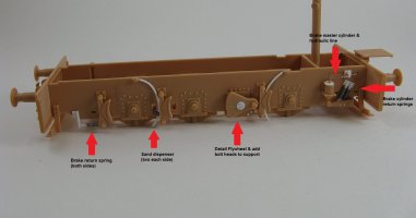 |
The following detailing was done at this point:
- Added missing bolt heads to the support plate for the flywheel axle
- Scribed a center line and added an axle end to each flywheel as per pictures on the walkaround [reference 3]
- Added sand dispenser pumps, pipes and pipe clips
- Added return springs to the front brake pads. As far as I could tell there were no return springs for the middle & rear pads
so none were added.
- Added return springs to the brake lever and a top cover and piping to the brake cylinder
|
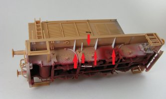
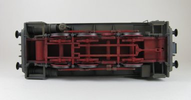
At this point I paused for some painting. According to reference [1] the inner surface of the frame and all parts inside the frame,
the wheels, connecting rods and flywheels were painted red. After applying the red paint I weathered everything with some washes and dry brushing using black, tan and
grey paints. I also took the opportunity to paint wood floor a light tan as well.
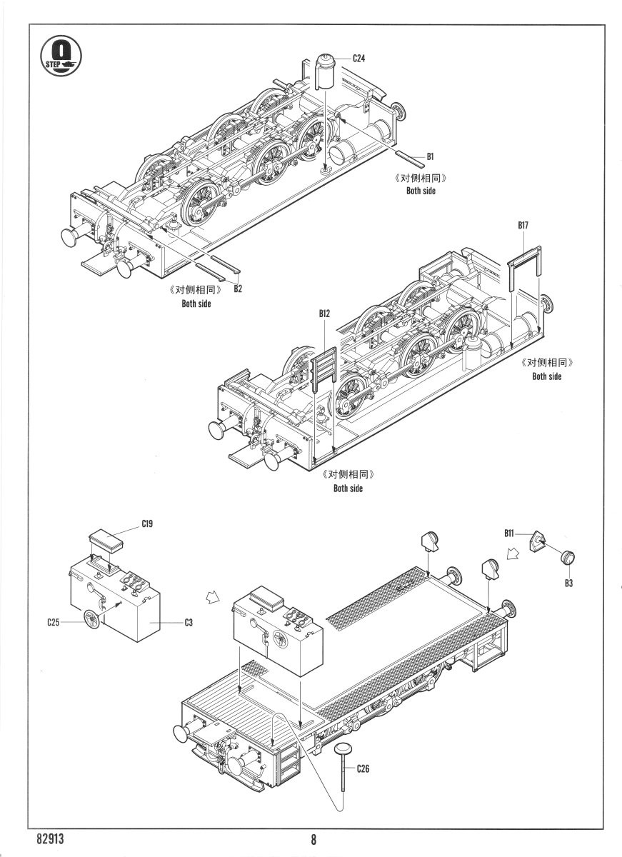
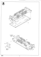
At Step 8 the first thing to do was fill the plethora of elector pin depressions on the underside of the deck (part A1).
As it turned out, most, but not all of them, were eventually hidden by other parts. The pressure cylinders (parts B13, B18) were assembled and put aside till nearer
the end of the build. The storage box (part C22) had hinges added and then it was glued to the deck.
 |
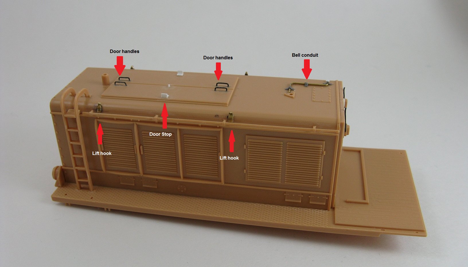
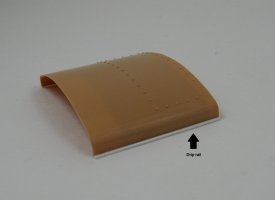
Here I deviated some from the instructions, first attaching the cabin bulkhead (part C7) to the engine cover (aka bonnet), then glueing
that assembly to the top of the deck. Missing detail was added to the engine cover:
- Pull handles to engine cover top access panel made from bent wire
- Door stops to the top access panel from plastic strip
- Lift hooks from scrap brass
- Brass wire for the electrical conduit to the horn and lead strips for straps
- Cover latch from plastic rod
I now added the headlights and their supports. The headlights were drilled out to accept lenses. The stanchions and ladder were also added here.
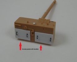
Hobby Boss has the exhaust pipe already drilled out which is nice. I would have replaced the molded on engine access panel handles
with some wire substitutes but there wasn't much room in which to work so I just left them alone.
|
Step 9: Undercarriage/Chassis pt.2 & Cabin pt.1
 |
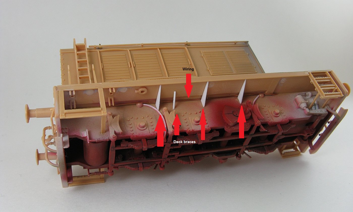
Once the paint was sufficiently dry the deck and undercarriage were glued together.
At this point I added more detail in the form of:
- Braces to the underside of the deck
- A wire running along the length in the angle of the chassis/deck join to represent an electrical conduit. From what I could see
in the reference photos there should be at least two conduits here, but I could only fit one comfortably.
|
 |
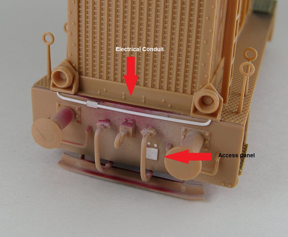
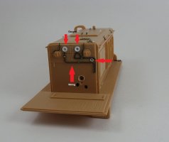
Some extra detail, an electrical conduit running between the
headlights and a missing access panel to the front panel, were added. |
 |
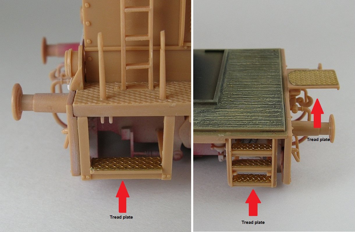
Then the steps are added. I did some test fitting first to make sure that my plan to squeeze
the pressure cylinders between the steps and the chassis later would work. Some brass tread plate was cut and attached to the top of the rungs with cyano glue.
The pressure vessel (part C24),
driver's seat (part C26), headlights (B3) and the steering wheel (part C25) all joined the growing pile of parts to be added later in the build. |
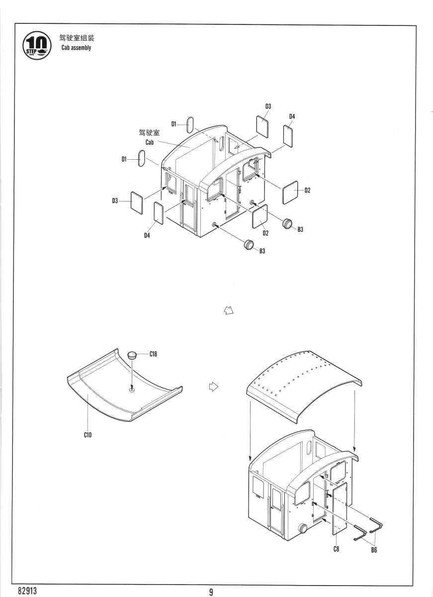
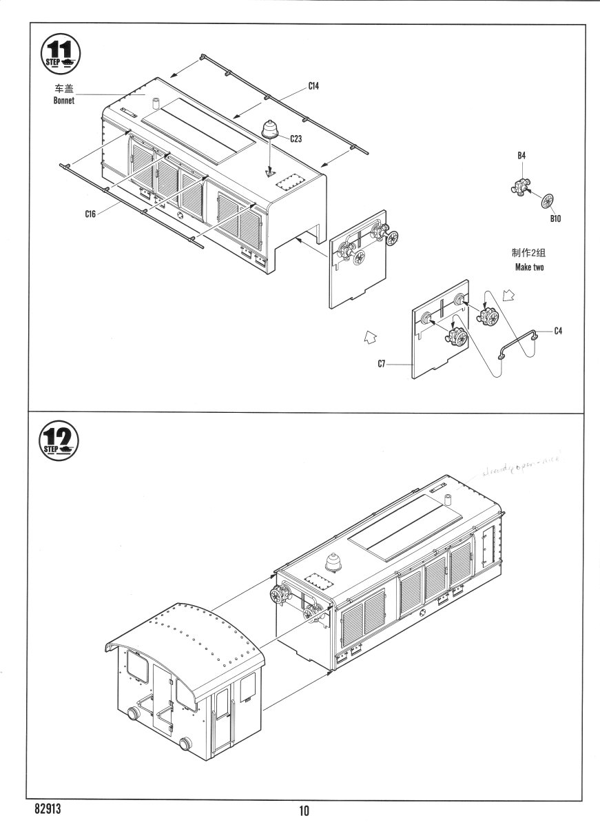
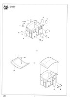
Steps 10 & 11: Cabin pt.2 and Engine Cover
 |
All the clear parts for the windows were separated from the sprue but not glued in place. They too were left for later.
The tail lights (part B3) and the cabin light (part C18) were attached and drilled out to accept lenses just like the headlights. A drip rail was added to the edge of
the roof (part C10). |
 |
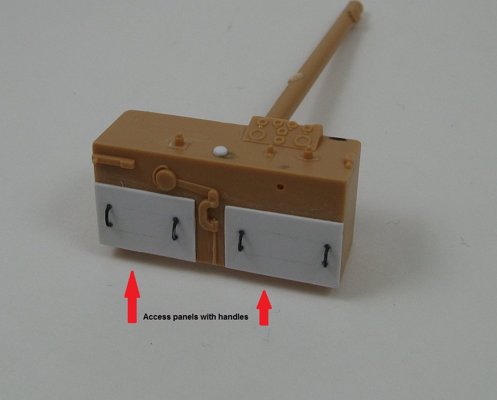
The operator's console was detailed some at this point. Since most detailing would hidden, it was limited
to adding access doors and handles and a missing knob. |
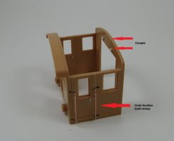 |
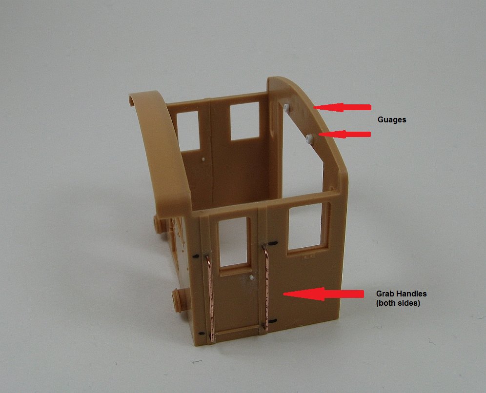
The kit's molded on cabin and rear door handles were trimmed from the kit parts and some simple replacement handles were added in their
place. Also molded on are the grab handles on to the cabin exterior so they too were cut off and
new bars bent from some thin gauge copper wire were substituted. I also added the bevels for two instrument gauges to the top of the cabin bulkhead. |
 |
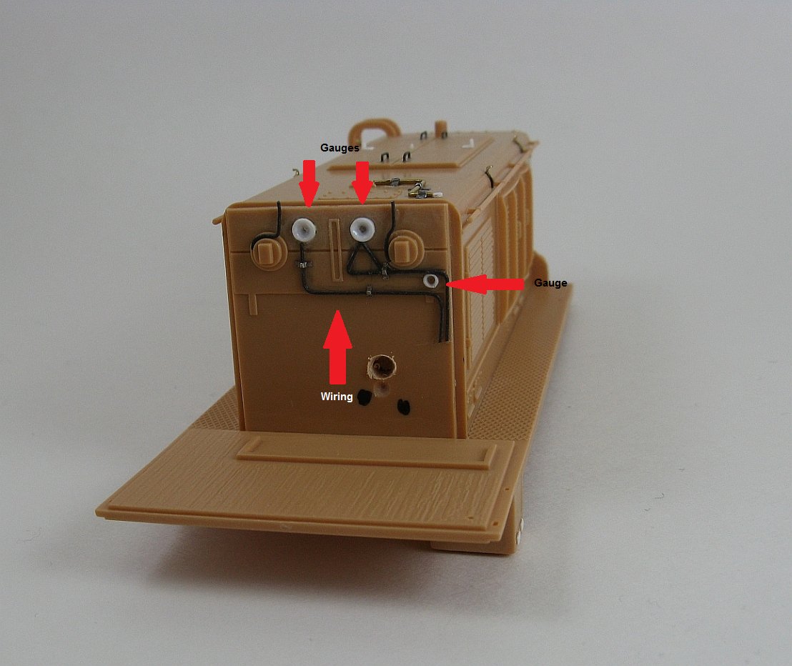
The kit only has the bare necessities regarding detail inside the cabin. The control wheels (part B10), bodies (part B4) and
connecting pipe (part C4) were added to the parts pile for use later. Using photos as a guide, some gauges and conduit were added to busy up the interior. A test fit of the operator's
console showed a notch was needed where the added wiring was placed to allow the console to fit against the bulkhead. |
Once again it was time for some painting. According to reference [1] the cabin interior had the upper half painted dark gray, the lower
half black and the ceiling in white. The cabin was then painted accordingly.
Afterwards I weathered the interior and sprayed on a flat coat. Then it was on to the exterior. I masked the interior of the cabin, ceiling and the red undercarriage and
applied the Panzer grey paint followed by some pin washes and weathering. With no decals to apply I then started adding all the parts and joining the sub-assemblies.
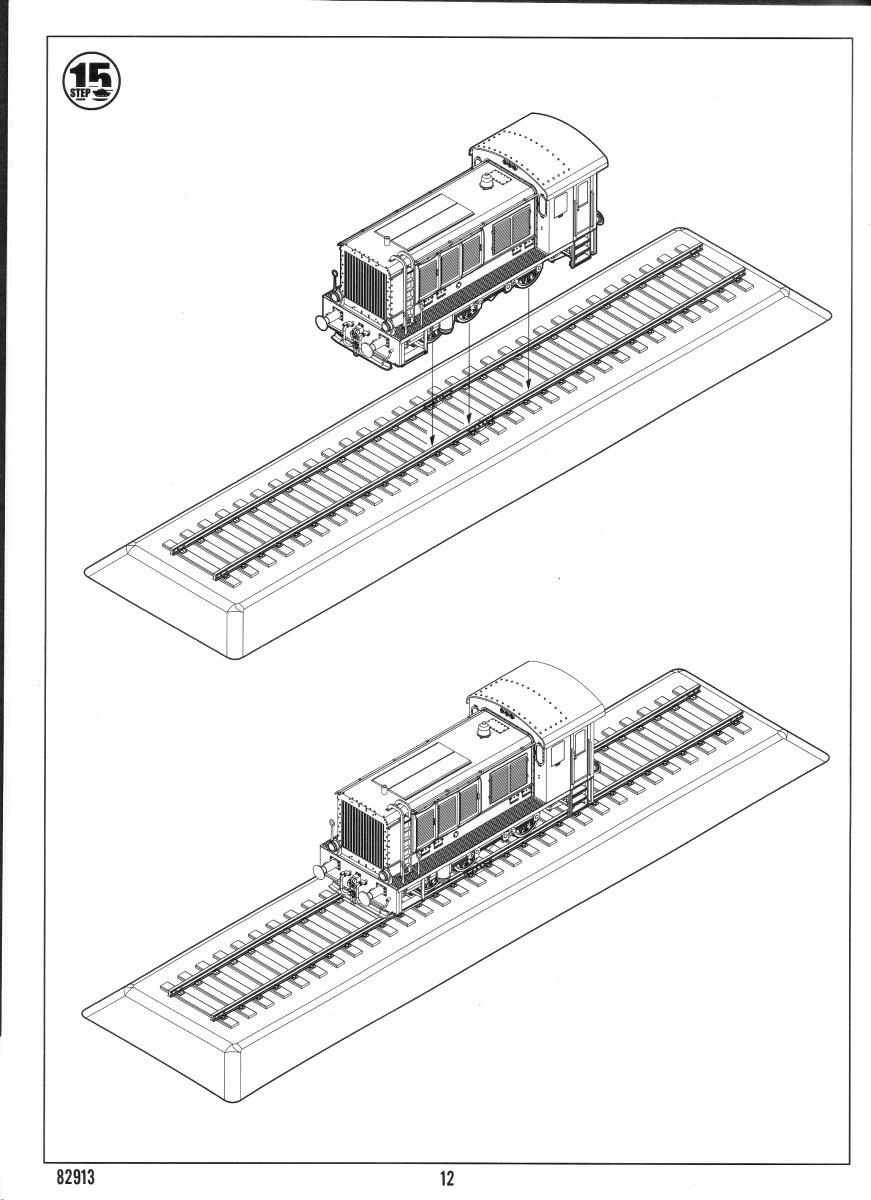
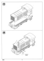
Step 12 through 15: Assembling the Body
Well, by this point I had pretty much completely deviated from the instructions which would have you add the cabin to the engine cover, attach that assembly to
the deck and add the ladder and stanchions. In my case final assembly went thus:
- Add the various parts to the cabin interior. These were the operators console, seat, control wheels & bodies, and the
connecting pipe that runs between them. A lens was inserted into the ceiling light and the roof attached to the cabin. All the instruments received a drop of white
paint to simulate the faces followed by a drop of 1-minute epoxy to simulate the glass. Then the cabin was slid into place and attached with some cyano
glue.
- Work then returned to the undercarriage again. I added, in this order, the two pressure cylinders, wheels, connecting rods and the
pressure vessel.
- Next was the front and rear lights. Lenses were made from circles punched from sequins with 1-minute epoxy to represent glass, and
once the epoxy had hardened the lights were glued in place.
- The cabin windows were a tight fit so some sanding along the edges was required to get them into place.
- The screw couplers were brush painted black, weathered and then attached to the front and rear hooks. Then the cabin rear door was
glued in an open position, with the hope that some of the interior work would be viewable.
A few paint touch ups were done here and there followed by masking in preparation for the flat coat. The cabin windows were only partly covered to allow the
flat coat to frost the edges. After the masking was removed from the windows a quick dry brush of some light tan was streaked vertically on the windows to make them look
a bit more grimy.
The only definitive measurement I could find was for length. According to Wikipedia the C14 version measured 9200mm from buffer to buffer, or just a hair over 30ft,
or approximately 5in in 1/72 scale. If the C12 was 35cm shorter, that would make it 8835mm, or about 29ft, and approximately 4.83in in 1/72 scale. My dial calipers measures the built kit as 4.81in, or very close to 1/72 scale.
Conclusions
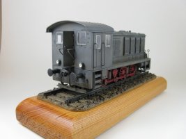
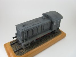
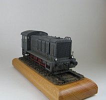
This is a very nice kit, even if it is of a subject that wasn't too common. Out of the box it would make an attractive model, while a few additions makes
it an even nicer kit.
References
[1] World Rail Fans forum
[2] rt-modellbau.de
[3] WR360 walkaround at panzer-modell.de
[4] Wikipedia (German)
Review sample purchased by the author.


|