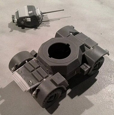
In
the box there are two light gray plastic mouldings, two metallic rods,
the instructions and a decal set which is the same of the Humber Armoured
Car kit. The details are sharp and the pieces flash free. The kit
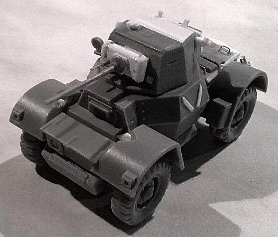
is quite well done and the general dimensions are correct. The turret
is a bit short and the hatch even shorter. The kit is a bit simplified,
for a nowadays kit a bit too much, but it came from the 70’s
when the standards were different; anyway being a good base it can
be easily detailed with a little working.
The
kit, as told, depicts a Mk II. A little problem arose when I begun
to search for useful photos and didn’t find them. So I tried
to understand when the Mk II production started. The only information
I’ve found was here: http://www.warwheels.net/BritishArmouredCarProductionFiguresArticleBROWN.html
where is stated that the Mk II production started in September 1944.
This is not a secondary question, because my preferred AFV subject
is the Normandy campaign. This forced me to modify my armoured car
in a Mk I. About my work, each time I discuss the Mk I conversion
I’ll point it out specifically, so one can ignore it if not
interested.
Below
I list the things I’ve done to add some details to my Daimler.
Anyway I ignored a good amount of screw heads: they were so tiny in
1/72 scale that simply the alternative for me was make them oversized
(and these look very bad, believe me).
|
Hull
•
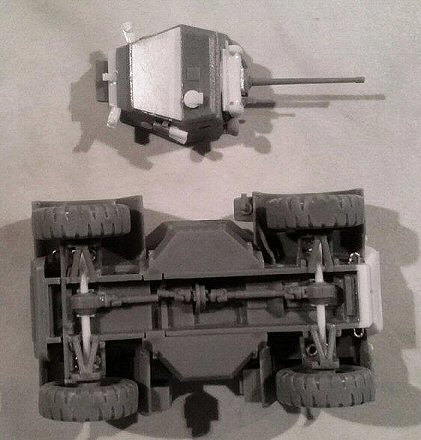
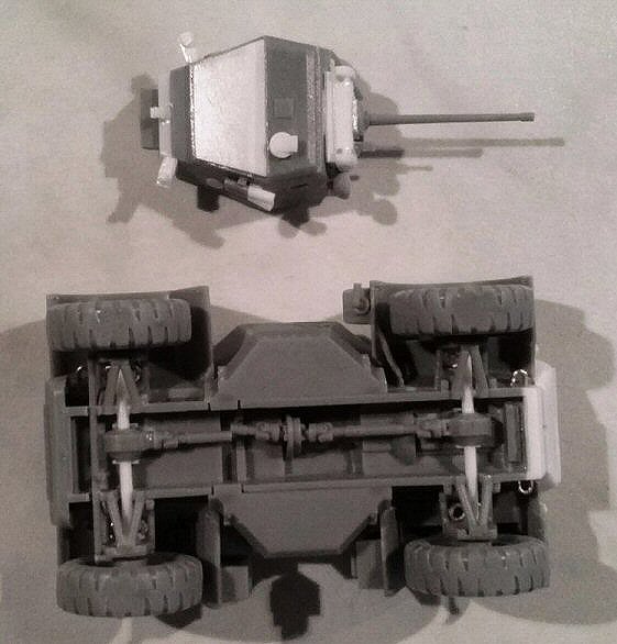
First of all, the chassis. It is sufficiently well made; anyway the
rear lower plate needs to be replaced in a sloped position. The right
angle is the projection of the sloped rear upper plate line. I filed
off the chassis rear plate and made a new one with plastic
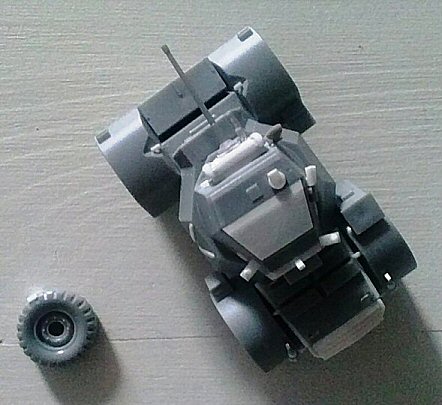
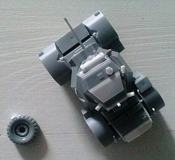
• Mk I: The engine deck had different cooling vents covers layout:
four smaller in place of the later larger two. The sides were widened
with two 0.5 mm x 1.0 mm rods smoothed with the upper sides.
• Mk I: The cooling grates were in the upper portion and the
portion where the kit has the grates was a solid sloped plate with
the side walls in line with the hull sides. Plastic sheets were used
to make the whole area. The crank hole was drilled in the centre.
• The engine deck received their four grab handles made with
metallic wire (yes, they were so high).
• The rear driving place had the vision slot engraved in the
rear plate.
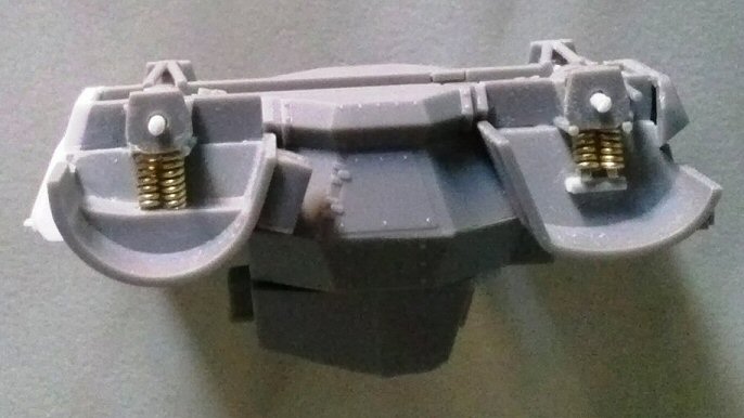
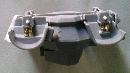
• The suspension is a bit too much simplified. To give it a
little more detailed look I replaced the wheels arms with 1.20 mm
plastic rods. To these I glued the pieces #16, which were lowered
and the corners clipped away. The upper arm of the pieces #15 had
their horizontal arms filed off before being glued; now new ones,
made with stretched sprue, were glued instead. Within the space above
the arms, I glued the suspension springs (two each) made with metallic
wire wrapped around the kit’s metallic wheel rods. The rearward
ones were fixed to the fenders inner roof, while the forward ones
needed a support made with plastic.
• The steering rod was made with stretched sprue in front of
the forward suspensions.
• The last thing I added to the belly of my Daimler was the
exhaust pipe from the engine wall to its box using stretched sprue.
It runs along the inner rear left fender and was bent as the original
one.
• There were four lifting points just over the wheel axles.
These were made with plastic and glued in place. The forward ones
needed the opening of their housing in the fenders.
|
|
•
The fenders were thinned on the transversal edge.
• The spare wheel needs the “V” shaped support on
the hull side and the bolting plate hole deepened and enlarged. Under
the wheel there was a folded plate.
• The rear mudguards had an inner rounded cut. I made it with
a sharp knife.
• The four towing points were made with the same metallic wire.
• I added the rear lights using plastic rod sections
• I added also fire extinguishers, made with plastic rod sections,
stretched sprue and metallic stripes.
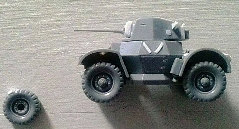
• The wheels are well done although they look a little too thick.
I didn’t find the correct width to confirm this, anyway they
look well and I kept them as they are. The three ejector marks were
sanded away. When gluing, I kept them slightly canted because in the
plans they are never showed vertical. After they were firmly glued
I flattened the ground contact points for better realism.
|
 |
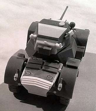
Turret
•
The turret is a bit short. I added a 1 mm plastic shim shaped in place.
• The roof had a gap at more or less 2.75-3.00 mm from the rear
plate, 0.75-0.80 mm depth (more or less). I erased the plastic from
the roof and shaped the hatch edge.
• The hatch is a couple of millimetres short. I made a new longer
one with plastic sheet to reach the new rear edge. The open hatch
must show the structure and the inner handles. I added the stopper
close to the rear plate.
• I added the pistol ports on both sides (2mm diameter)…
• … and the small port on the left side of the front.
• The side vision slots were engraved in the plates at 5.00-5.20
mm from the lower edge.
• The periscope was enlarged with a rounded piece of plastic,
cut toward the front. A rectangular cover was made with plastic.
• I scratchbuilt the two antenna bases with plastics strips
and rod segments. |
 |
•
The smoke dischargers were only fixed on the right side in every photo
I’ve seen. It is a bit undersized and short. I added two plastic
rod segments in front of the kit part, glued inversed to respect the
instructions and paying attention to the slightly diverging firing
angle.
• Mk I: A new mantlet was needed. After having closed the hole
I made it with a piece of plastic (11.00 mm wide, 5.00 mm high and
2.00 mm deep) two thin stripes and a sloped shim (the mount) on the
back. The gun was glued to this with a hexagonal base. The kit MG
was placed and the gunsight hole was opened in a short rod segment,
both parts were added on the gun sides. Here the bolt heads are large
enough for them to be realistically represented with stretched sprue
segments sanded down once the glue was dry. |
|
 --------- --------- |
Decals
Two
vehicles are suggested:
F208338 it is a very generic armoured car of the 7th Armoured Division
in Egypt. The serial is a correct Mk II census number; being part
of the first batch. However since the Mk II was built later in the
war, its African operational engagement must be fictional.
F208944 it should be a “T” census number for an Universal
Carrier and not for a Daimler. I didn’t find its photo, however
the Daimler vehicle depicted looks exactly like F208148 (or 145?)
which was a Mk I (see here: http://www.documentingreality.com/forum/attachments/f240/159558d1272446628-post-battle-berlin-fuehrer-bunker-1945-british-armored-fighting-vehicles-daimler-mk-v-passing-russian-soldiers.jpg
). The AoS number 44 background is wrong, being black instead
of blue over green.
The markings aren’t well-defined, but comprise also the serials
F26979 for a Humber Armoured Car Mk II, two little red A Sqn triangles
and a couple of divisional badge for the 1st AD, 7th AD and 10th AD,
always useful for other projects.
Conclusions
Conclusions
Well, this kit looks like a nowadays quick building kit, but it is
fundamentally correct and can be easily detailed. The decal set is
really poor and a new one would be welcome. As far as I know, actually
it is the only Daimler Armoured Car plastic kit on the market. A resin
upgrading could be a good inspiration for a kit maker…
References
on history
and technical data : http://www.daimler-fighting-vehicles.co.uk/
Some
walk arounds :
http://www.primeportal.net/apc/de_craecker/mk1_walk.htm
http://www.net-maquettes.com/it/pictures/daimler-armoured-car-mk-walk/
|
| Preview
sample purchased by the author.
This
model can be purchased from

|

 ---------