|
Aurora-Esci
|
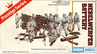
Nebelwerfer Battery |
|||
| Kit #: 6212 | Review by Al Magnus - one72guy(at)hotmail.com | |||
|
Aurora-Esci
|
Nebelwerfer Battery |
|||
| Kit #: 6212 | Review by Al Magnus - one72guy(at)hotmail.com | |||
 |
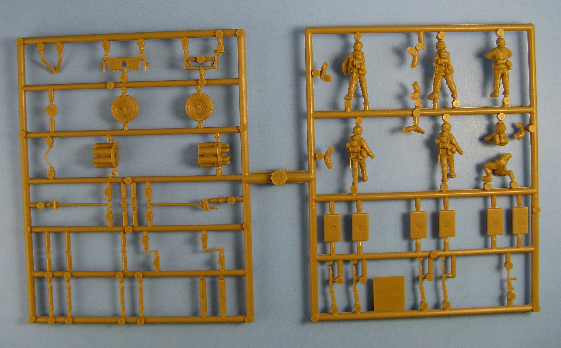
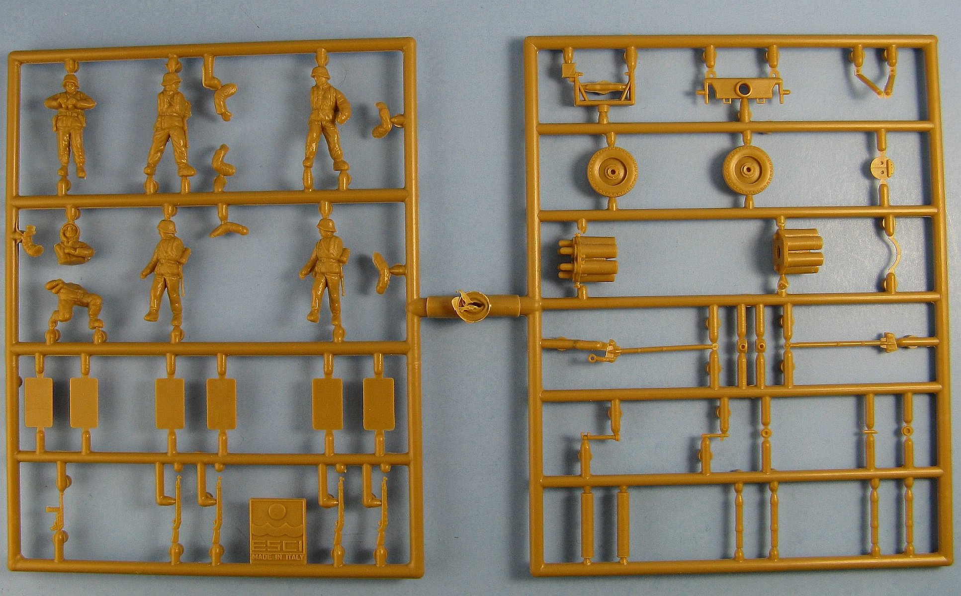
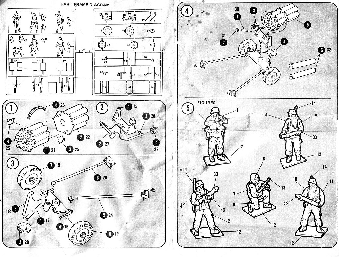
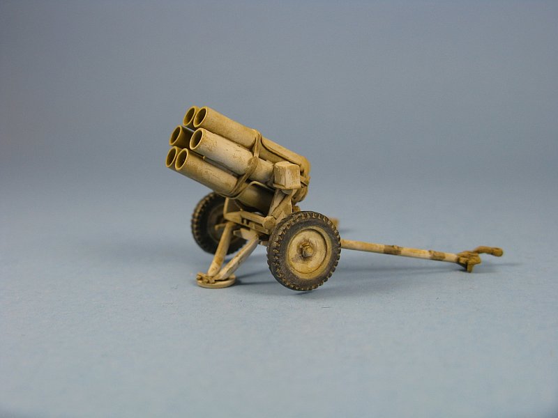
Step 1: Before doing any gluing the much too narrow tubes holes need to be drilled out. This I did in stages using increasingly larger drill bits to widen the holes. If you want a "see through" look to the tubes as I wanted, the molded on rockets at the end of the tubes have to be removed and then the solid bulkheads on each end of parts 21 and 22 need to have holes drilled through them. For the towed launcher I also removed the bottom end of the tube and added new sections from plastic tube. For the launcher in firing position I just opened up the end and left the molded on tube in place. The pivot brackets (2xpart 25) that mount to the tubes are a problem and I decided to put them on a later point. If added as per the instructions the toothed elevation gear (part 23) would not touch the elevation shaft (part 27) and there will be a big gap between them. Also the tubes will sit too high in the mount and look odd. Step 2: The mount (part 15) has a prominent seam that fills most of the hole created between the brace and the upright. For both launchers, I cut off the brace, removed the seam and added a new brace from plastic strip. The elevation wheel (part 29) was left off to be added later to lessen the chances of it being damaged during the remainder of the build. 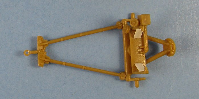

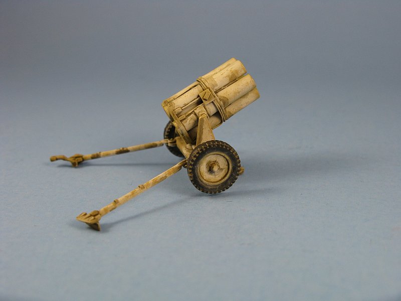
Step 3: This is the step where the carriage is put together. First, the spades on both launchers were thinned. For the towed piece I glued the trail legs together and modified the front support braces into their folded position for travel. The one in firing position was constructed as per the instructions with the legs splayed and the brace deployed to touch the ground. Since none of the kit wheels (2xpart 19) were not up to snuff I substituted different ones. On the towed Nebelwerfer I used a set of Esci Pak35/36 wheels. The hubs on these were poor so I removed them and added the hubs which were cut from the kit's wheels. On the other I used a set of wheels liberated from a MAC Flak38. All the wheels were also left off until later so they can be painted separately. Step 4:
The two hand wheels for traverse and elevation (parts 29 & 31) were glued onto their shafts this point. With the thought that I may at one time try to put one or both of the Nebelwerfers in a diorama, I put together two of the figures and separated the rockets from the sprues. Removing the rockets (4 x part 33 ) requires some care. Make sure to cut them from the sprues leaving some of the injection gate in place so you can sand the tip of the rocket to its proper pointed shape. The transport tubes (2 x part 32) are not as detailed as shown on the instruction sheet and they suffer from large injection holes. I chose to replace them with scratchbuilt examples made from plastic rod with end caps punched from some plastic sheet. I added grab handles from spares found taken from a depth charge etched brass set. 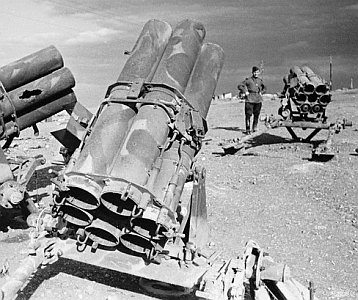
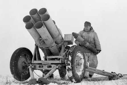
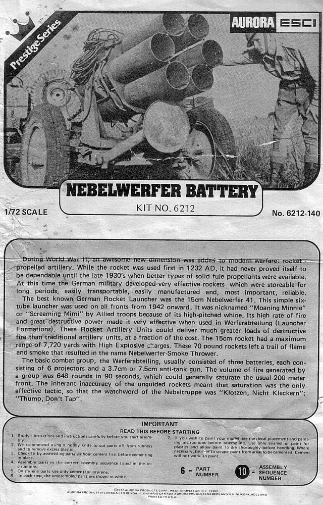
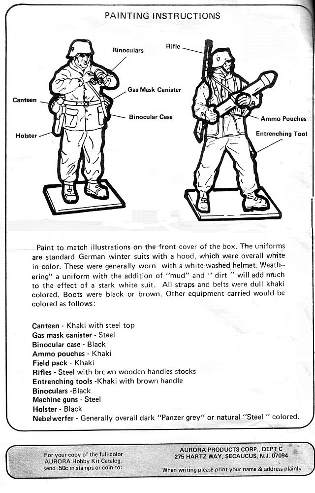
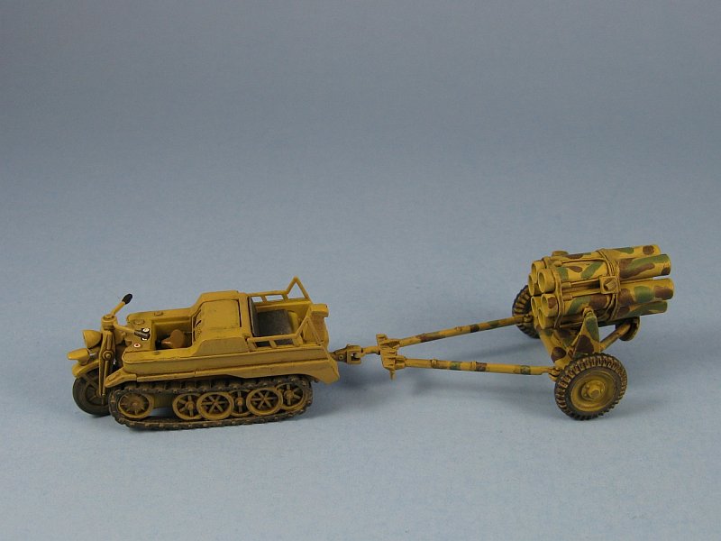
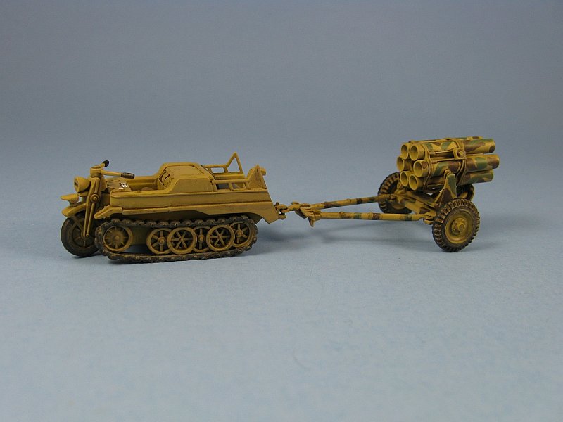
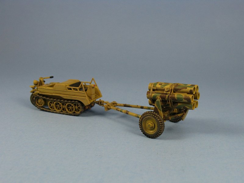
Painting: Painting is pretty straight forward. You can choose whatever German camouflage scheme you desire since Nebelwerfers were in use from 1940 til the end of the war. I chose to do both in the light tan camo with one in winter whitewash and the other having green and brown splotches. (insprirational photos above) There has been some debate over the years as to the kit's scale. I don't have much data on the various dimensions of the Nebelwerfer 41. What I do have gives the tube length as 51 inches. In 1/72 scale that works out to .71in. My dial calipers measure the kit's length at .71in, making the Esci kit exactly 1/72 scale as far as the tube length is concerned. I'll just have to assume that the rest of the kit's dimensions are somewhere in the same ballpark. This kit is showing its age. My copy had a copyright date of 1977. Though the quality of the moldings are passable, especially when compared with some of the limited run injected offerings, the detail is not, which requires the builder to go that extra mile to make an acceptable model for display. What is really odd, is that after all these years, the Esci kit remains as the sole injected plastic Nebelwerfer available to the 1/72 scale modeller, which is why it still commands a fairly sizeable dollar value when it shows up for sale on online sites like eBay.
Review sample purchased by the author. |
| Back to Esci/Ertl Kit List | Back to Construction Reviews |
Article Last Updated: 15 March 2011 |
Back to Home Page |