|
The Kit:
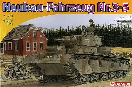
With box art work by Ron Volstad, the Neubau-Fahrzeug NR. 3-5 (kit no. 7438) comes in a larger than normal box and it is taped on all four sides and
shrink-wrapped. There are over 90 pieces for assembly, none of them being metal or photo-etched brass.
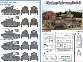
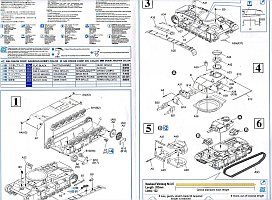
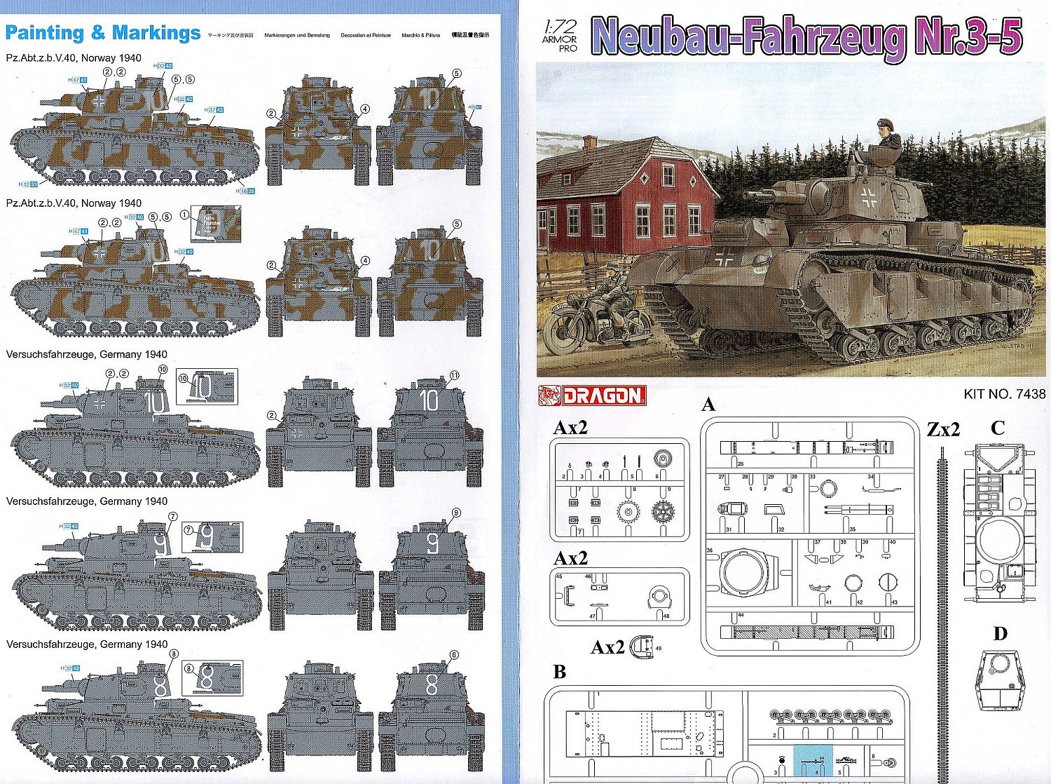
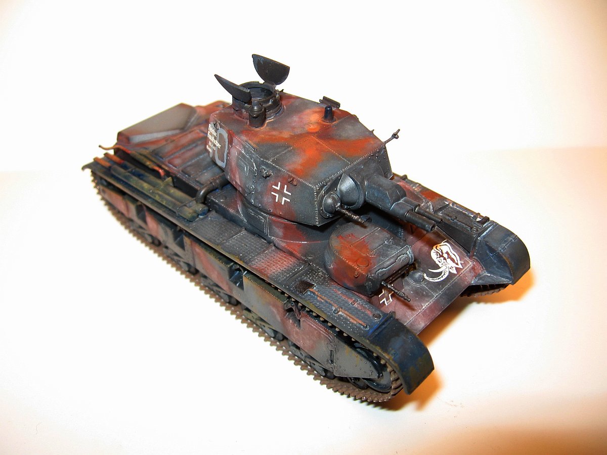
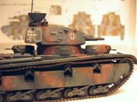
There are only six steps to assembly and five decal options - though three of the markings are only to number the vehicle
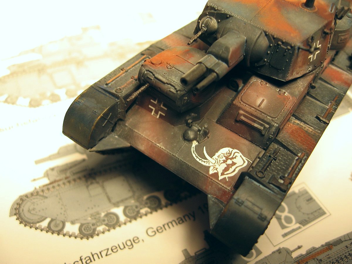
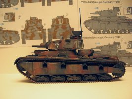
8, 9, or 10. The Norway markings have an Elephant or Woolly Mammoth head decal for the top front hull position for Pz.Abt.z.b.V 40.
An axe is the only part not used and is shaded in blue on the instruction sheet. The track length guide is of dubious value. Other than
stating the needed length, Dragon should just plainly state "If too long, trim. If too short, stretch".
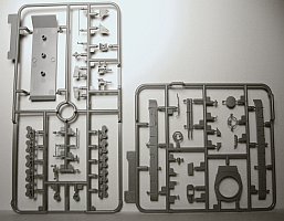

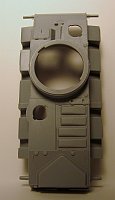
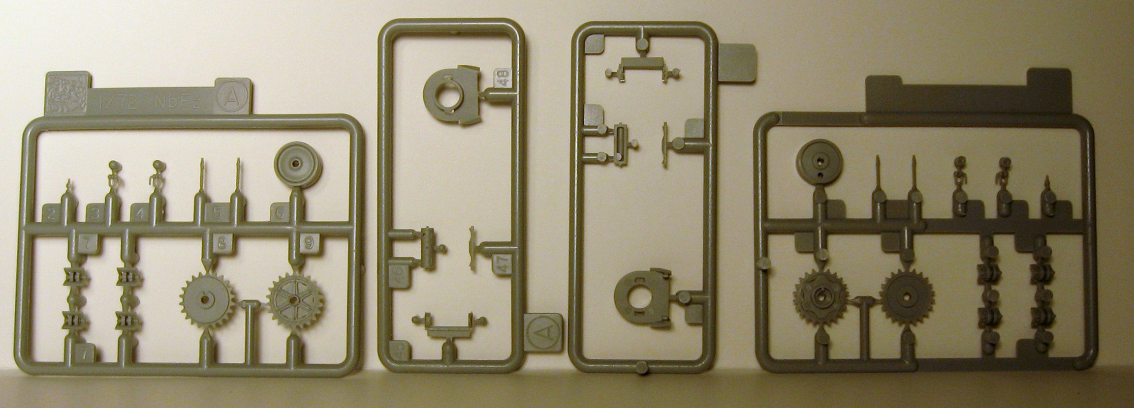
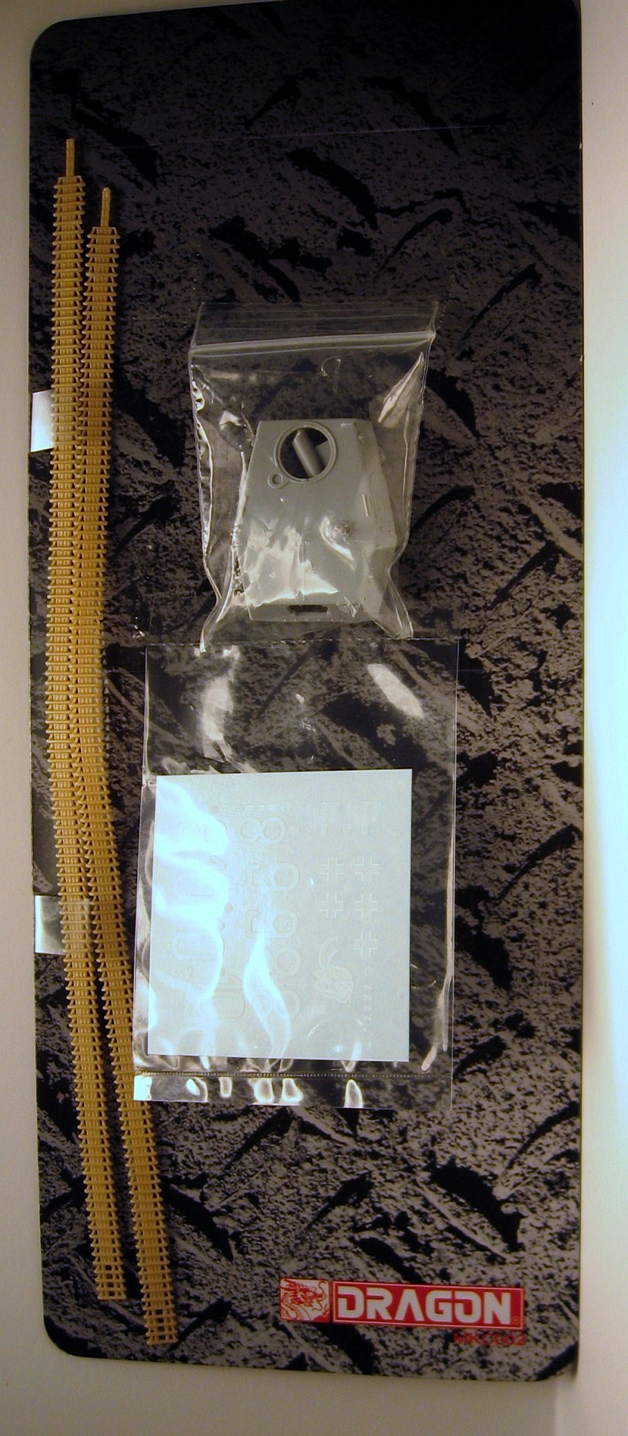
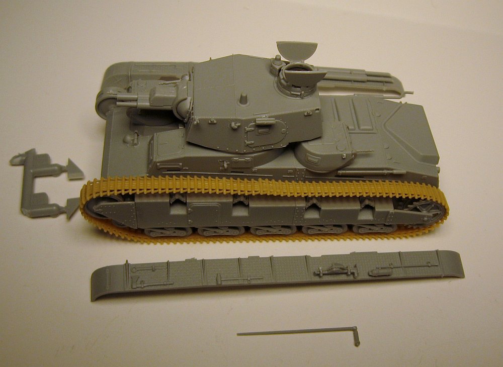
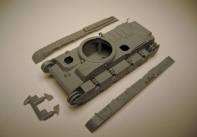
The six sprues, header card with turrets, tracks, decals and the separately bagged hull, leave the interior of the large box quite sparse.
Sadly, while our 1/35th scale counterparts are getting increasingly more difficult with more detail and parts, Dragons efforts in 1/72
are regressing. All hull and turret hatches are molded closed except the commander's hatch on the main turret. You will have to split
the hatch yourself to even achieve this. Also of note, the hull has screw posts as well as does the bottom hull pan which has finely
done rivets and detail on the bottom.
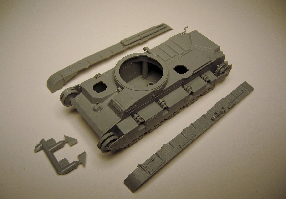
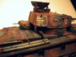
The next major detail piece to be both over detailed and under-whelming at the same time are
the two fender pieces.
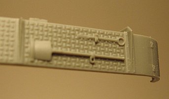
Beautifully rendered tread plate is let down by molded on tools that have finely molded hold down buckles,
yet another tool, possibly a slug wrench, is faintly molded.
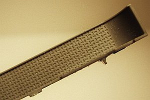
Another oddity is that the fine tread pattern on the fender is repeated on the underside where it can't possibly be seen within reason.

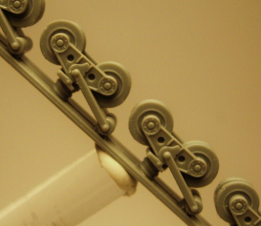
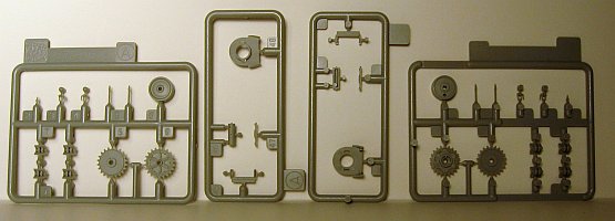
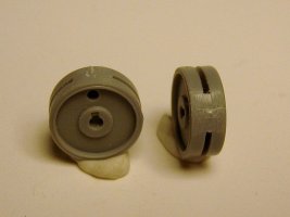
Moving on to the road wheels, we see they are molded in one piece with a separate single road wheel that goes under the front idle wheel.
It is also molded in one piece. The sprockets are molded in halves. The top return rollers are molded separately, four on each side.
Overall, I would like to have seen all the hatches molded open on this vehicle, and it is a bit of a let down in this respect.
Recent releases from Dragon are proving that they are not afraid of releasing rare or odd-ball topics and the part count and detail level
is a compromise between the Ready-Built market and construction model market. I believe this is a strategy that will continue in the future
and even more recent releases bear this out. The Golden Age of Modeling marches on.
The Build:
About 35 pieces, with at least six being downright tiny, make up steps (1) and (2).
STEP (1)
You would think it wouldn't be necessary to sand the seams on top of the running gear (B11 & B12), but you should, as they are
resting on the ribs inside of the upper hull.
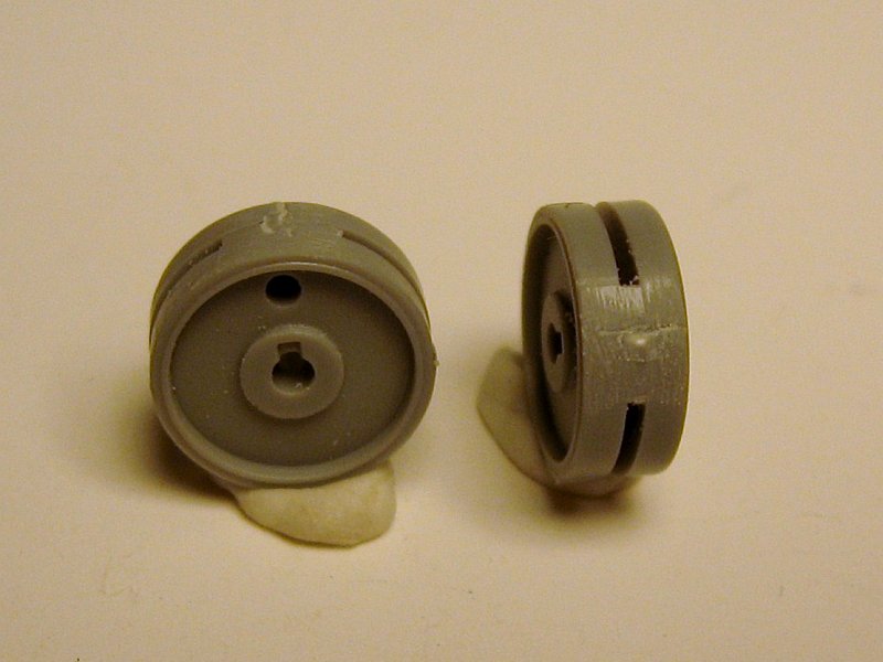
After clipping the large idle wheel (A6) off, you will see the space near the drain hole is solid.
Position both idle wheels so this is hidden by track or hull parts. Make the location of the wheel's drain/lightening hole different from each
other for variation. When it comes to placing the tracks, you may have to account for that filled in spot on the wheel by either trimming off
track teeth or rotating the wheel. Parts B17 and B18 are tricky. I had to trim off the circular locating piece on the inside of part B17. When
it came to putting the return rollers in place, I found it difficult to keep them in a straight line, and at the proper elevation in relation
to each other even though there are marks or "shelves" for this.
STEP (2)
Step 2 is a few hull pieces and the placement of the left fender. I will hold off putting the fenders on, making it easier to place and paint the
tracks and return rollers and the spaces in between.
STEP (3)
Very similar to step 2. If you are going to leave off the fenders like I did, the fillet pieces (A38, A37) must be left off as well.
STEP (4)
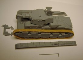
In this step the main turret is constructed. I mounted the turret ring to the top turret half and began the assembly of the twin main gun mount. The
guns have a minimal movement in the up/down motion, so too much glue here is no big loss.
I had no problem making them elevate. The commanders coupula directions seem to have swapped part numbers. Build it as it is pictured, not as it
numbered. (A42 is really A33. A33 is really A42) The parts diagram on the front of the instruction sheet are correct. I split the commanders hatch
myself, for a figure later. Put all the small pieces on last.
Decide on a lowered antennae B12 and B13, or raised one.
STEP (5)

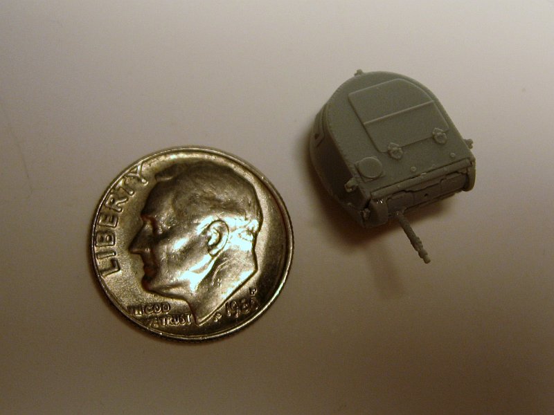
Step five is only the construction of the two machine gun armed turrets. Six pieces make each turret.
STEP (6)
Lastly, step six is a little redundant. It only consists of placing the already constructed turrets on the hull and the placement of the tracks.
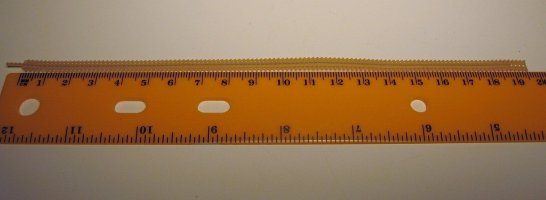
My tracks measured 195mm out of the 203mm needed for the correct length. Stretching will be required in my case.
To add some length I just gently stretch the tracks with my hands with no more than an inch or two of track between my fingers at one time so as not to
snap the track. I prefer to stretch the track in runs and leave them sit for a day to make sure they don't shrink back to their original length.
This is a nice weekend builder. I did lose a marker light for step three, where a hole was required to be drilled in order to mount it. Not a big
deal. Rather not go drilling on the curved side of the hull anyway. The part is so small, I probably didn't see it still on the sprue. I had alignment
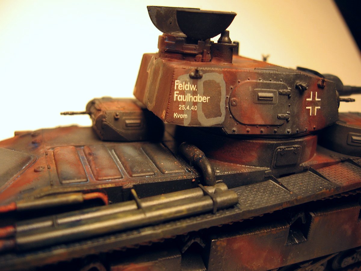
issues with the top return rollers as mentioned. If you paint your model in the Norway 1940 versions, I have to add that you must "paint out" the "10"
decals with a color lighter than the base color.
Review sample purchased by the author.


|