|
Historical
background:
From Tanks
Encyclopedia:
The
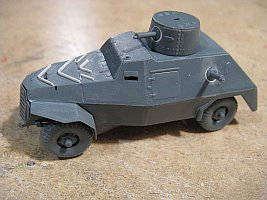
Marmon-Herrington Armoured Car was a series of armoured vehicles
that were produced in South Africa and adopted by the British Army
during World War II.
The Mark II, which appeared in November 1940, differed from the
Mk.I in having a slightly longer wheelbase, real four-wheel drive
and welding assembly. 338 vehicles were built of the British “Middle
East” (ME) version and 549 of the MFF or “Mobile Field
Force” (MFF) version, which is represented in this kit.
The initial armament was unchanged in the Union Defence Forces (MFF
version), with two Bren-guns (one in the turret, one in ball mount
on the left side of the hull), but the British ME version, serving
in North Africa, received a redesigned turret equipped with an extra
Boys 14 mm (0.55 in) antitank rifle, with a coaxial Bren 7.7 mm
(0.3 in). It was later equipped with additional mounts for an extra
AA Bren and/or a rear AA pintle mount for a Vickers cal.303 (7.7
mm). The British/Commonwealth Mk.II in North Africa were often rearmed
with various captured armaments (German 3.7cm Pak 36, Italian Breda
20mm gun, ...). This led to the elimination of the turret, the operating
crew being protected by the gun shield. A
fair number of Marmon Herringtons was also used
by the Germans after capture.
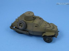
What
is inside the box
Inside the cardboard side-opening box, there is one plastic sprue
and two identical decal sheets. The parts are well rendered with
thoughtfully placed ejection marks. Very little flash is present
and detail is sharp (perhaps not up to the level of companies like
Flyhawk, but more like what I am used to from UM). The wheels and
MGs are perhaps the weakest parts; the former having unconvincing
thread detail, while the latter are a bit soft in detail.
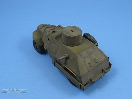
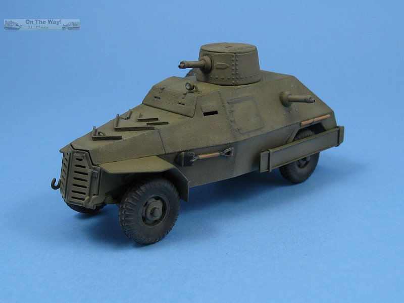
No interior is present and while the armored shield for the windscreen
can be positioned open, the windscreen itself is solid and would
benefit from having clear plastic inserts where the windows are.
The sand channels are of the solid type, which can be seen on the
real vehicle, but those who want can replace them with an alternative
perforated type from an aftermarket company.
Detail for the lower chassis is given, which might be partially
visible as the vehicle has a rather high stance.
_t.jpg)
_t.jpg)
_t.jpg)
Two
identical decal sheets are given. I am not sure why, as the second
sheet is only needed to get a total of four "RHQ" decals,
but one can never have too many spare decals.
Instructions, decals and painting schemes
The
instructions are clear (even though the English, and especially
French, text might benefit from more proofreading) and should not
present any surprises, although it is somewhat strange to see the
numbering sequence go from VII to IX, with no VIII. A small correction
sheet for the instructions is provided for step II.
_t.jpg) _t.jpg)
_t.jpg)
Some
parts in the parts diagram are marked as "not for use",
with some of them removed from the sprue, while others are retained
to serve the modeller who is hungry for more spares. While I cannot
inspect the removed parts, the diagram would make me believe that
the Middle East version will be released soon as well.
_t.jpg)
Three
marking options are provided for vehicles serving in 1941. Colors
are given for Humbrol and Agama. Online conversion tools can be
found for those of us that use another preferred brand.
Conclusion
This kit confirms that Attack is
continuously improving the quality of its kits, while, at the same
time, daring to offer kits of vehicles that are not as mainstream
as your run-of-the-mill T-34, Sherman, or E-100.
Additional comments from Al Magnus (17/Aug/2016)
With the kit in hand, I agree with Rob's observations above. In addition to his comments I'd like to add the following:
- Two of the marking options, RHQ & 'Digh Merer', are the same as those that appear on the
IBG 1/35 scale Marmon-Herrington Mk.II Mobile Field Force (MFF) kit.
- The rim-to-tire interface could be a bit more pronounced to help with painting. The tire tread is
odd looking and doesn't match any tread pattern I could find in my references.
- Fenders (parts 46 & 47) are reasonably well done. Attack has bevelled the outside edge to make
them appear thinner but the bevel can be seen when the fender is viewed edge on. I plan to extend the bevels further towards the body to reduce their conspicuousness.
- On the instruction sheet the sprue layout shows parts 28 & 29 darkened to indicate that they
aren't used, but at the same time there is mention of using them later in
the instructions as alternate parts. I could find nothing in the assembly diagrams calling them out.
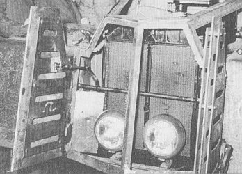
Checking my references these are the radiator (part 29), and the vertical brace with the twin headlights (part 28). I would assume that they would be used should the
modeller wish to expose the radiator or to have something other than a void visible behind the protective cover.
(refer to reference picture below).
- For me the biggest travesty with this kit comes with the windscreen. For some head-scratching
reason, Attack has molded the windows solid. This is something that you'd expect with some of the 'quick build' manufacturers, not from a company that is marketing
their kits as detailed replicas. Why this piece wasn't molded in clear plastic puzzles me and I'm not sure how to approach fixing it. I suppose one
option is to button up the vehicle by attaching the armoured cover over the opening and discarding the windscreen panel.
Build update by Al Magnus (30/August/2016)
I have commenced construction of this kit. In addition to the comments above I have the following to offer.
- There should be handles for the rear doors and one for the engine hood.
- If one has the armoured windscreen cover in the open position the modeller should add the curved rod used for opening the cover.
- I was unable to tell from the poor period photos available, but there may be weld lines where the hull plates join.
- The chevron deflectors on the top of the hood are poor, and should really be replaced.
- Wheel hubs are all identical, being the extended type suitable for the rear axle only. According to
photos found in [2] & [3] the front hubs are much shorter and have rounded covers.
- The solid sand channels lack side extensions seen in period photos.
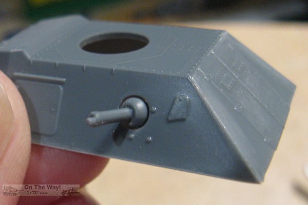
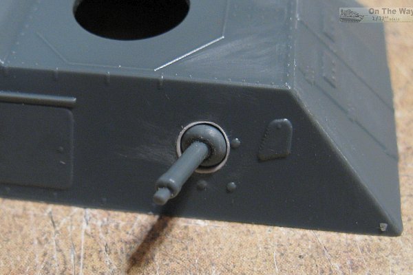
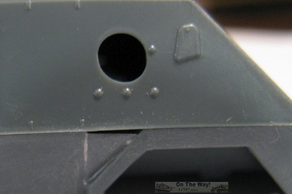
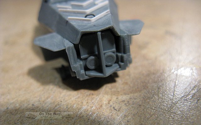
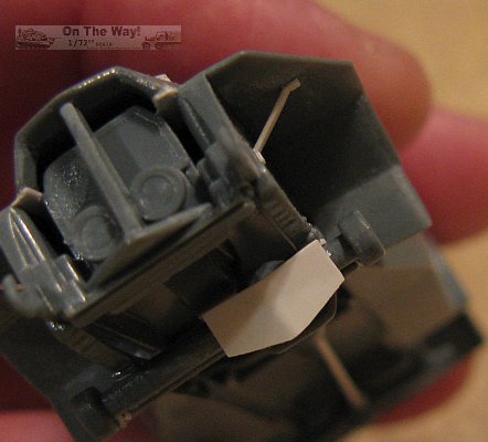
- There is a serious flaw with the MGs and their associated openings, as shown below.
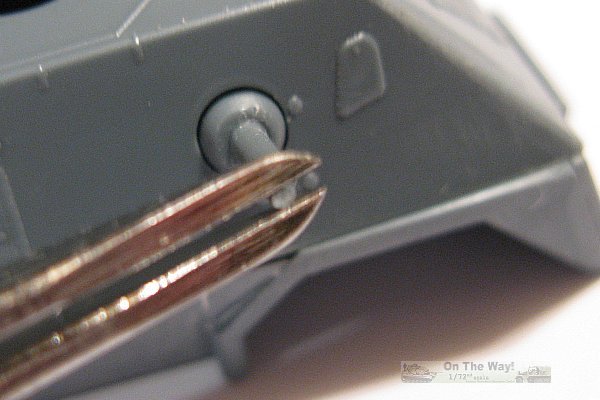
You can sure tell that nobody at Attack bothered to build up a test example of this kit, for if
they had I assume this problem wouldn't have got to the production release. The circular
opening is too large for the MG ball mount allowing the MG to slide right through the hole,
and with nothing for a backing, the gun just falls into the empty interior cavity. |
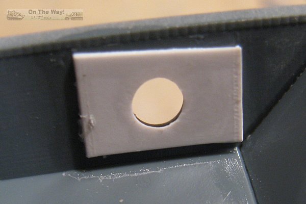
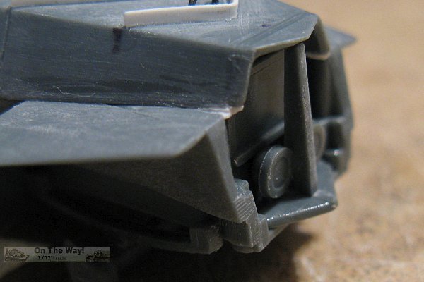
My first try to fix the problems was to add a slab of plastic sheet with a hole in it
and glue the slab to the inside of the hull centering it's hole with the MG's opening. |
View of my first fix from the exterior side of the hull. |
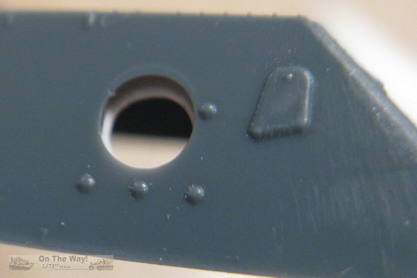
Here is the MG held in place in the new hole. As you can see the gap is still there and all
I've accomplished is preventing the gun to fall into the inside. Oh well, the beauty of
working with plastic is I can just pry off this failed attempt and try something different. |
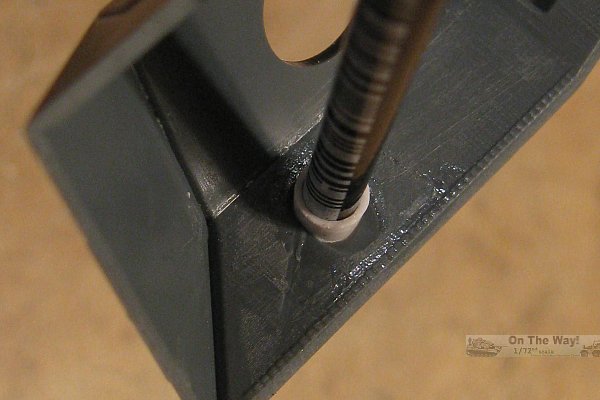
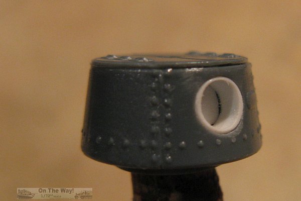
This is attempt number two. This time I took some plastic tubing and
tapered the end to fit the hole from the inside. Now there is no gap. |
Here is the view of attempt number two from the outside. A trial fit of the MG shows that I
will need to trim the ball somewhat to get it to fit, but
at least I now can add the MG
at a later time and not worry about it falling into the inside. |
The plastic tubing is in place and the ball for the MG has been reduced. |
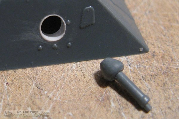
The end result of attempt number two. A trial fit of the MG shows that it still can
barely slip through the hole into the interior, but I'm certain that it will fit nice
and snug once the paint and some thin cyano glue are applied. |
Note: the too large hole applies to the turret MG as well. Whatever is done
for this fix will be visible should the modeller decide to open up the hatches to reveal the turret's interior.
|
Gap between the left side upper and lower hull parts after
fitting the small triangular piece (part 55). |
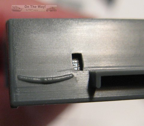
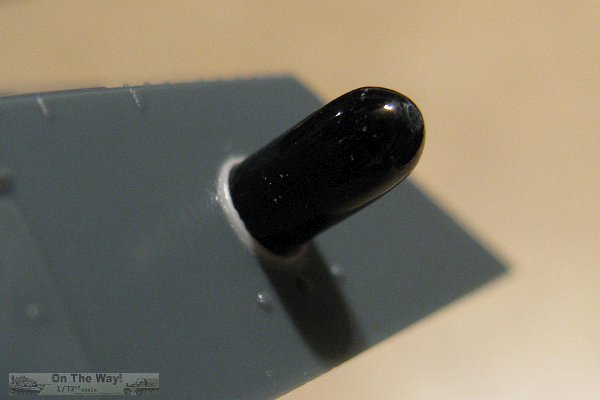
Extremely poor representation of the axe head mounted on the rear hull.
This definitely needs to be shaved off and replaced! |
|
|
| I have found two tire styles in my references. On the left is the civilian looking tire tread pattern that seems
to be the norm for the MFF version. On the right is the large lug tire style that seems to be the norm for the British Middle East version. Note also that the MFF
rims are of the slotted variety while the ME rims are a solid disc style. The kit has the Middle East tread version with MFF slotted rims. And it appears that
Attack took the easy way out and used the Middle East style tire for this kit and possibly the soon to be released ME kit. Modellers wishing to have proper MFF style
tires will have to make their own or wait for the aftermarket manufacturers to produce them.
|
So as it stands right now, the kit is proving to be more trouble to build than first anticipated. Fit problems need to be addressed, poor detail needs to be replaced,
and there is just enough flash and seams to remove that is starting to make the build a bit on the tiresome side already.
Build update by Al Magnus (02/September/2016)
The build slogs along. Along with some minor work on cleaning up parts such as the tires, some major reworking has been performed.
First of all, here is a pic of the kit tires.  As you can see the tread pattern matches
quite well with that of the tires in the ME version pic above. As you can see the tread pattern matches
quite well with that of the tires in the ME version pic above.
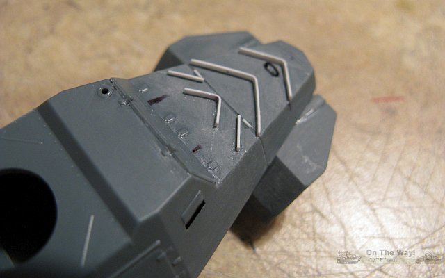
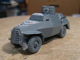
The poor deflectors on the hood, which were not much more than slight bulges, have been replaced with the thinnest plastic strip I could safely use. They look
much better but etched versions would be the best solution. Maybe the upgraded Profi Line release (kit no. 72902) will have etched deflectors. I've also added the
missing handle. |
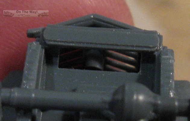
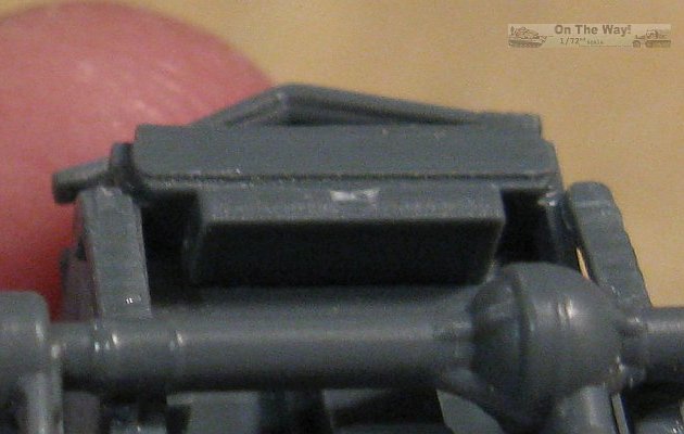
The photo on the left shows that without the radiator the hollow inside of the body is visible along with the huge ejector pin found on the rear face of the
protective cover. Needless to say, that pin needs to be removed to fit the radiator. The right photo shows the radiator in place. This looks much better
but there still remains a void between the protective cover and the front of
the radiator. |
This photo shows the lights (part 28) loosely placed in front of the radiator. The triangle piece under the lights covers over the remaining void between the radiator
and the protective cover. This is nice. Unfortunately though, the angled vertical brace is too big and prevents the protective cover from sitting flush over the opening. Not a
problem if you plan to cut the cover and display it open, but if you do open the cover, then there should be a bulkhead added behind the radiator to block the view into
the hollow interior. |
Mounting the suspension is not fun. The lack of placement points on the chassis along with the vague instructions leaves the modeller with a by-guess-or-by-golly
proposition. Once I had everything glued in place, but before the glue had set, I attached the wheels with some blue tack and adjusted as required. The only major
problem found was the left front wheel was left floating in the air, so I separated the axle at the left front spring mount and inserted a couple of thin plastic shims.
This got the wheel to touch along with its brethren. I also found that the links on the front axle that the tie rod attaches to are too thick and interfere with
the wheels. These were trimmed. The drive shafts are nowhere near round and should be replaced.
Build update by Al Magnus (05/September/2016)
There is light at the end of the tunnel! Most of the major changes have been completed and now I'm focusing on the small parts - tow hooks, muffler/exhaust &
spotlight, plus drilled out the openings for the MGs.
As mentioned above, the vertical brace is too big to allow the radiator cover to fit nicely. To remedy this, I've cut back the brace some to get a good
fit (above left). You can also see the small pieces of white plastic sheet used to fill the gap between the fenders and the engine hood.
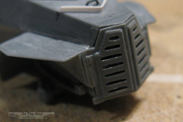
After some scraping and sanding the radiator cover fits quite nicely (above right). The radiator cover had a lot of flash in the cooling slots
that had to be removed. As you can see removing the flash makes it difficult to get the openings to match each other. I plan to give them a bit more attention to
hopefully make them look better. |
The biggest surprise was how well the turret went together. Outside of having to add a spacer to the MG opening similar to what I had done for the hull MG, the multi-part
turret actually went together quite well. Just make sure you get the two semi-circular pieces (parts 45 & 49) in the proper places, otherwise the seam for the
hatch on part 4 will not line up with the back seam of the turret. Just ask me how I know this! |
A real head scratcher comes with the exhaust system. Made up of three separate pieces with the pipes butt joining to the muffler, getting them to line up
properly is a real pain. I resorted to turning the vehicle over, temporarily taping the muffler to the body, and then gluing the pipes in place, and allowing
everything to set overnight. Afterwards I removed the tape and had a nice exhaust system that I can paint separately and add later.
Build update by Al Magnus (08/September/2016)
This is the last update before painting and applying decals.
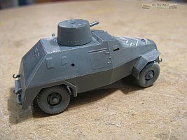
A quick sanity check was done to make sure nothing has changed suspension wise, so the wheels were temporarily added and the stance checked to make sure all
wheels touched the ground. The bracket on the rear hull and the tow rings have been added. The small black dot is where I figure the spare tire will be mounted. The
instructions are woeful in this respect. |
More changes here. The fender braces and the front differential shield have been added from plastic stock. I was not sure of the shape for the differential
shield so I checked the web for a 1/35 scale IBG shield as a guide. In the fuzzy background is one of the two replacements for the drive shafts. |
So now the model is about 95% complete. I still need to add a few minor items and then decide what to do about the poor sand channels. I think the kit parts will need to be
tossed and new channels made from scratch. Got my fingers crossed that I can make two identical and acceptable replacements!
Build update by Al Magnus (10/October/2016)
As I approached the end I realized that I was not going to get this kit to the level I felt was appropriate for a contest model, and switched over to trying a few
new techniques and to hone my scratch building skills.
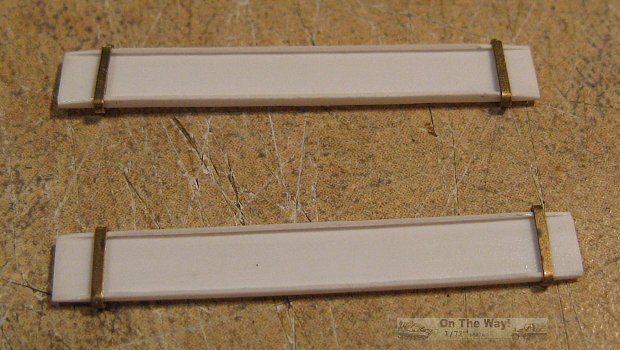
First on the agenda was replacing the sand channels with scratch built items which I feel really look the part versus the kit's very basic versions. For the fun of it,
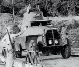
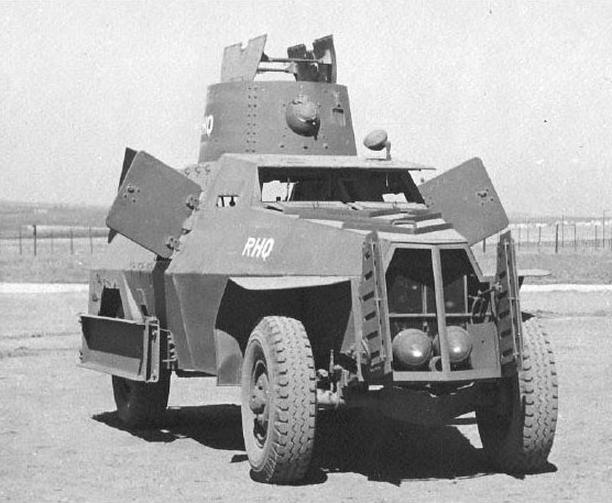
I added silver sequins to the headlight faces before covering them with the radiator cover. I was curious to see what they would look like hidden behind the
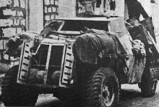
cover. On the real vehicle the rad cover is a sandwich affair which would block any view to the lights or radiator, as seen in the picture below.
So a modeller wishing to replicate the look should, at minimum, add an additional layer to the back of the cover and space it just a tad to leave a small gap.
With construction finished, paint and markings were applied, or should I say an attempt to add markings was made. Unfortunately the option I
chose, the decals with the white RHQ enclosed in a black rectangle, was a disaster. After dipping in some warm water the decals literally disintegrated when touched
to move them from the paper onto the kit. So my Marmon is now just a generic vehicle. So be warned, apply some decals film, like that offered by Microscale,
over top of the markings before applying them.
With painting done the various sub-assemblies were joined. It was at this point I realized that the trimming I had done to the the tie rod links was insufficient making
the attaching of the wheels very difficult. I should have replaced and relocated the links to ensure a good fit. I also noticed that the front wheels almost touch
the rear portion of the front fenders due to the axle's placement, an oversight on my part when test fitting the wheels previously.
So was the build worth the time. Well, kinda. I did get to practice some scratchbuilding, but on the whole I was left with the feeling of a big waste of
my time when all was said and done.
Upon opening the box, the kit looked oh so close to hitting it out of the park. Alas, construction revealed that
it was closer to a routine fly ball to centre field. The poor fit, omissions and weaknesses in detail let this kit down measurably. Those wishing to build
a contest worthy Marmon will need to address the faults I have mentioned above, and go at the least one step further to rectify the incorrect tires and radiator cover.

References
[1] AFV Weapons Profile 30: Armoured Cars Marmon-Herington, Alvis-Straussler, Light Reconnaisance, B.T. White, Profile Publications, Windsor, Berkshire 1971
[2] www.aviarmor.net
[3] www.warwheels.net
[4] www.ibgmodels.com (IBG Models 1/35 scale Marmon-Herrington MFF)
[5] www.pwm.org.pl
[6] www.track-link.com
Review sample provided by Attack.
This model can be purchased from

|
.jpg)


.jpg)
.jpg)
.jpg)
.jpg)
.jpg)
.jpg)
.jpg)


