| Unimodels |
www.onthewaymodels.com | M32B1 Tank Recovery Vehicle | ||||
| Kit #: 225 | Preview
by Stephen ‘Tank Whisperer” Brezinski Edited by Marc Mercier |
|||||
| Unimodels |
www.onthewaymodels.com | M32B1 Tank Recovery Vehicle | ||||
| Kit #: 225 | Preview
by Stephen ‘Tank Whisperer” Brezinski Edited by Marc Mercier |
|||||
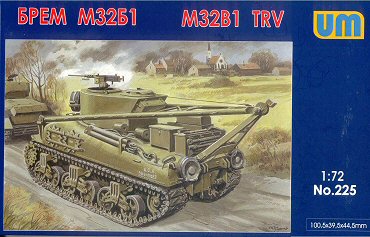 |
The M32B1 is a WW2 and Korean War period Tank Recovery Vehicle (TRV) based on the M4A1 medium tank. According to my references, when the number of M3 medium tanks ran out to convert to M31 TRVs, the M32 TRV was developed. To be exact, the M32 TRV was based on the M4 tank chassis, the M32B1 is based on the M4A1, the M32B2 on the M4A2 tank, and the M32B3 is based on the M4A3 medium tank. All of the M32 variants were converted from existing tanks except for 111 M32B1 TRVs, which were built new. During the construction period, there were many improvements and the vehicles also underwent field modifications by their crews so in examining period photos, we may see a lot of variation from one M32 to another. What We Are Supposed To Have In The Box On the drawing left we see what appears to me to be a stock M32B1 as it might appear from the factory based on the neat appearance and lack of stowage. |
||
| Starting at the top we see the fixed, rounded, turret bolted to the turret race with 50 calibre machine gun on an open ring mount and behind it an escape hatch similar to the commander’s split-hatch cupola of the early-mid production M4 medium tank. The initial production M32 used a flat-sided hexagonal fixed turret. Affixed to the turret we see a spare roadwheel and a storage box. There is a support cable running from the A-frame peak up to a fitting on the left side of the M32B1. On the sides of the A-frame are small lines that represent ladder-like steps for climbing the A-frame. The hull is the rounded cast steel hull of the M4A1 tank. Near the front is a rack with two spare drive sprockets. Some M32 and M32B1 had the spare sprockets mounted on the turret sides, some on the hull sides. Up on the port (left) hull side we see a pair of tubes that are used for towing recovered vehicles. On the rear hull are several spare roadwheels and an A-frame support for the A-frame crane during travel mode. Up on the engine deck are storage boxes, hand tools, and what appear to be spare return rollers. At the rear corner of the engine deck, we see the teardrop-shaped grouser-compartment cover that appears to be turned around 180 degrees from its normal orientation (I used to think these were small engine vents). Turning to the suspension: the drive sprocket is the initial style often referred to as the "fancy" style of sprocket wheel. The heavy-duty Vertical Volute Spring Suspension (VVSS) bogies appear to have the solid spoked wheels, but the wheel type appears vague to me. The M32B1 is painted in olive drab colour with minimal markings visible, only a vehicle number. The roadwheel’s rubber tires are painted dark gray. From the scenery the TRV appears to be set in NW Europe. |
|||
 |
 |
||
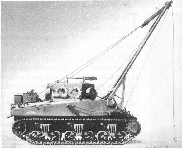
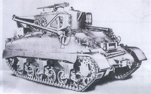
| Here
are a couple of old US photos from a technical manual. The photo right
shows an M32 or M32B2 (based on the welded hull construction) with the
A-frame crane raised forward and with the associated support and winch
cables deployed. Notice the small A-frame support still attached to
the peak of the crane and with cables running back to the rear of the
engine deck. Spare drive sprockets are affixed to the side of the fixed
turret. At the base of the A-frame crane, on the starboard (right) side
is a triangular bracket to support the A-frame off the glacis.
The photo
above shows the TRV with the hexagonal fixed turret. On the front
of the turret we see a long, small, rectangular hatch which I understand
is for a winch cable. Looking back to the left-hand profile photo,
we can see a cable coming from this location and going up to the peak
of the A-frame. In front of the turret is mounted an 81-mm mortar
which I believe was used for suppression of enemy fire and laying
a smoke screen. However, most M32 wartime photos I have examined do
not have this mortar. |
|||
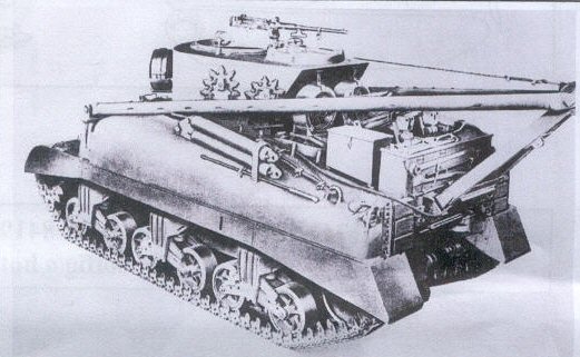
The A-frame crane is folded back and we see the raised hinges attached to the glacis and hull sides. This particular M32 has a 3-piece bolted differential cover and a 57-degree angle glacis with direct vision (DV) hoods. The DV hoods and small driver’s hatches indicate this is a conversion from an early Sherman; wartime photos show appliqué armour on the driver’s hoods, but none on the hull sides since it did not carry ammunition.. Welded onto the differential cover, we see a tow pintle similar to that mounted on the rear of many Sherman tanks. On top of the glacis is a box with rollers visible that appears to be a port for a winch cable; I have found one photo of an M32 in WW2 with a looped cable clearly hanging down out of this box. The Kit Parts Most of this M32B1 kit contains the standard hull and suspension parts included within UM’s M4A1(75) kits. Unimodel’s Sherman kits are modular, with parts designed for multiple Sherman variant kits, so expect some extra unused parts such as extra roadwheels and engine decks. I counted about 150 green colour, injection moulded, styrene plastic parts on nine sprues with four sprues particular to the M32B1 model kit, not including about 50 parts for the link & length tracks. There is one sprue named F containing 30 about etched brass parts. The plastic parts are well done, but overall not as detailed and more simplified than the average Revell, Trumpeter or DML kit. The UM etched brass parts a welcome plus but are not as finely done as that from Eduard, DML or PART, for example. The two Sprue-A containing the tracks and wheel parts is the same as that included in other UM Sherman kits using VVSS bogies. Good news is that the open cast roadwheels (parts 5A) that UM included for the model are the correct 5-spoke style; in the initial UM Sherman kits they gave us incorrect 6-spoke open wheels. I do not see any reason why these parts cannot be used with a 1/72-scale M4, M4A1, M4A2 or M4A3 kit from UM or another manufacturer to create other versions of the M32 TRV. |
|||
|
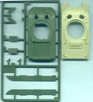
Left
are the UM M4A1 upper hull (part 20C) that comes with the M32B1 kit
next to Retrokit’s M32B1 upper hull part at right. The UM hull
is the early production M4A1 hull with the two small oval driver’s
hatches and therefore commonly referred to as the small-hatch Sherman.
The Retrokit M32B1 is based on ESCI’s old big-hatch M4A1 hull,
a hull common to some M4A1(75) DD tanks and to M4A1(76) tanks. I have
not seen an actual count yet, but I have read that few M32 TRVs were
based on the M4A1 big-hatch hull, and if they were produced, it is
unlikely they served in WW2, but perhaps Korea and Cold War Europe?
The hull of the UM M4A1 could use a little cast-steel texture, such as by stippling the plastic with a stiff brush and liquid cement to soften the surface of the styrene or with a textured coat of Mr. Surfacer. For a review of Unimodel’s M4A1(75) kits please go to: www.172shermans.com/kitreviews/UM/M4A1 and www.172shermans.com/kitreviews/UM/T1E3. |
||
Sprue D at the right holds parts for the fixed turret, turret fittings and the storage box (part 16D) that mounts on the rear of the engine deck. The hatch ring is simplified and moulded onto the turret roof (part 11D); I am unsure if this hatch ring was fixed in place or rotated as on the Sherman turret. At right are the two Sprue H included in this UM kit holding spare roadwheels (23H), sprocket wheels (62H) and the brackets (parts 64H and 9D) for holding the base of the A-frame crane. |
 |
||
|
|
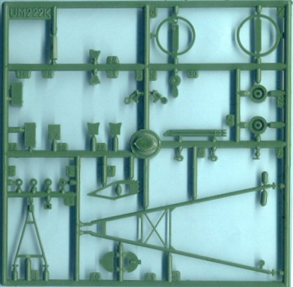
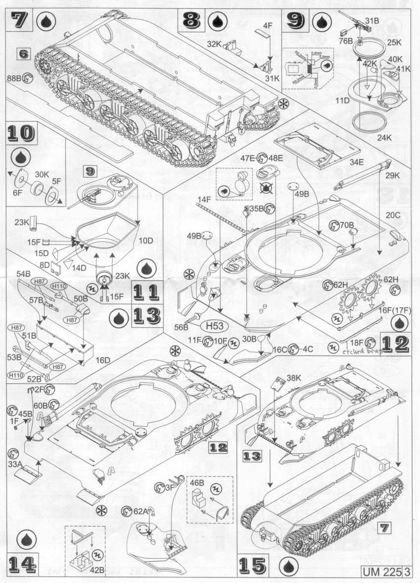
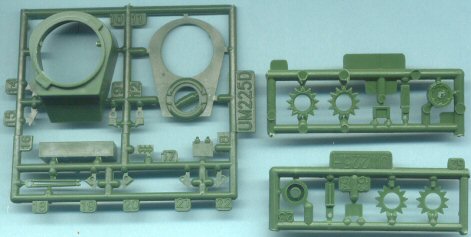
Sprue
K is another sprue particular to UM’s M32B1 kit number 225.
This sprue contains the turret machine gun ring (parts 24K and 25K)
at top right, the A-frame parts at the bottom (parts 26K, 27K, and
28K). Kit Instructions Below are instructions focusing on assembly of the Tank Recovery Vehicle parts of the instructions. Like other UM Sherman kit assembly instructions, they are multi step, black & white line drawings. I have found them complete but can appear very busy so should be studied well before and during assembly. If you wish to see full instructions for this model kit I suggest you go to Henk’s magnificent website at: http://henk.fox3000.com/um.htm On the left in Steps-7 through 15 are instructions for assembling the fixed turret and associated M31B1 parts. In Step-11 and Step 15 we see an attachment of small doors (parts 8D and 38K) for winch cables that, with a little work, could be modelled open. The spare sprocket wheels (parts 62H, 16F and 17F) could be mounted on the turret side, so see your photo references of a vehicle you wish to model. If you wish to model a driver’s hatch open, you may wish to use a spare small-hatch from a Dragon Sherman kit as the Dragon parts have improved underside detail. In Step 14 we see the instructions of UM’s little jigs (parts 42B, 46B) for bending the headlight and tail light guard parts (etched brass parts 2F and 3F). I glued my jigs onto a strip of thick plastic and use them with brass Sherman parts from Eduard and Dragon as well.
|
||
|
 |
||
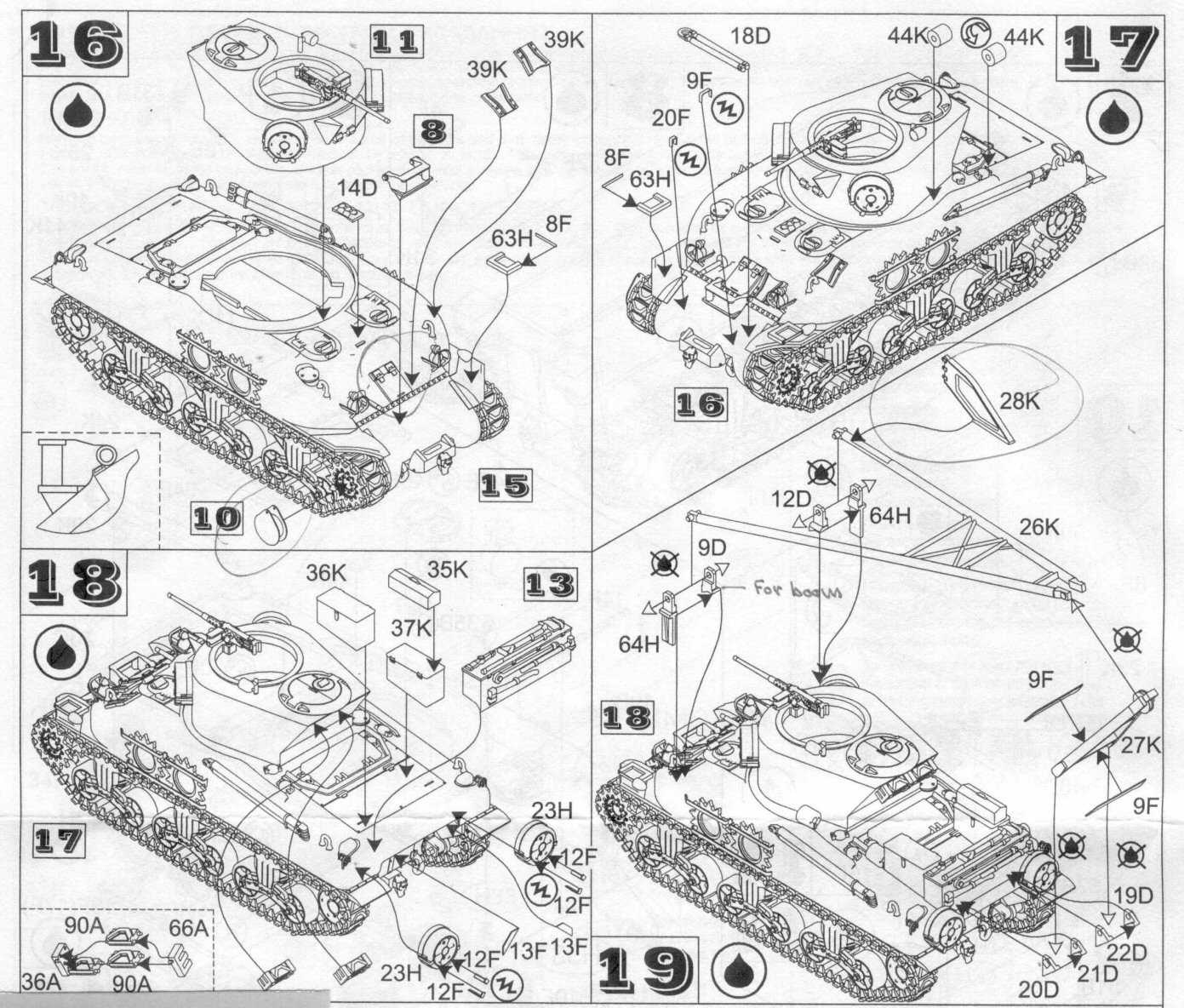
| On
the right drawing, Steps 14 though 19 cover the final assembly of the
M32B1. We can see that the forward machine gun ring is open with a decent
visibility into the empty turret. For a good display model some added
interior detail will be needed or perhaps a figure to fill this empty
space.
The A-frame crane is shown in travel mode but, with studying photos of the real M32 TRV, we should be able to accurately model this vehicle with the crane positioned forward. The A-frame does not have the steps seen in the box art and in reference photos; these can be replicated with a drill bit, fine wire and a lot of work. Notice in Step 18 that sets of spare track links are mounted on the rear of the turret where on the box art there is a storage box there. Some TRVs had nothing in this location, some had rolled tarps stowed there. |
|||
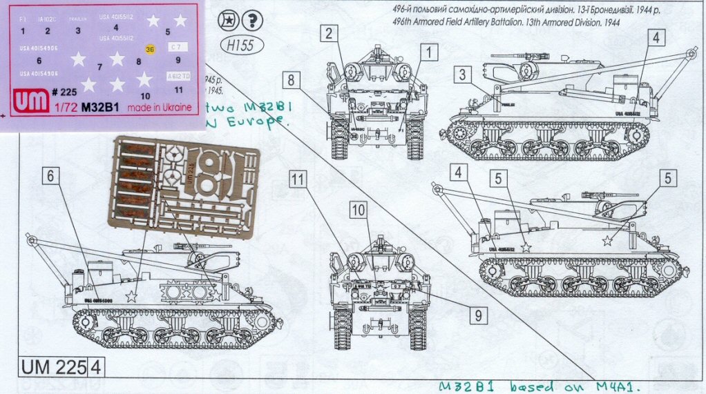 |
UM
offers two 3-view line drawings showing location of the water slide
decal markings included in the kit for TRVs serving with the 496th Field
Artillery Battalion and the 738th Tank Battalion in NW Europe. In historical
photos, I have seen a wide variety in the location and type of markings.
Vehicle names were also popular. On one M32 photo a spare sprocket wheel
partially hides a white star on the hull side. The
etched brass fret particular to this UM kit is left of centre. |
||
| Here
are several more old drawings of the M32B1 from Retrokit’s assembly
instructions for their kit. This is the vehicle represented by the UM
model kit, an M32B1 based on the small-hatch M4A1 tank hull. On this
vehicle, the spare sprockets are stored on the turret and there are
spare track mounted on the rear upper hull rather than spare roadwheels.
On the bow are the hold-out bars (parts 18D) used in towing vehicles. In the left photo part of the sandskirt is removed and there is an unusual rounded plate affixed to the sprocket wheel which is the lifting drum. This rounded plate is included in UM’s M32B1 kit as parts 5F, 10F and 30K, and is shown in assembly steps 10 and 16. A boom-lifting cable is attached to the lifting plate and then to the boom lifting arm. When the TRV drives forward the cable winds around the drum and lifts the A-frame boom into place. |
|||
  |
|||
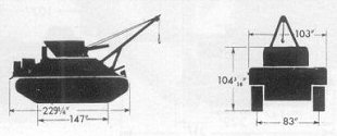 |
This profile will help in determining scale of the complete TRV. Notice that this silhouette shows the M32 carrying a dummy gun on the fixed turret, something that I have not seen on actual M32 TRVs. | ||
| Conclusions I am very pleased that UM released this kit, the first styrene plastic M32 TRV in the 1/72-scale and it is more historically accurate than the Retrokit M32B1 which itself based on the accuracy-challenged ESCI M4A1 kit. The plastic is a bit softer than that used by the likes of Revell and Trumpeter but that also means it is easier to sand and shape and the glue bonds quicker. From previous assembly of UM Sherman kits I found that fit of parts is generally good, but not as good as Revell and Dragon for example, so expect to need model putty and do some sanding. No material to simulate the cables are included in the kit, but sewing thread with a light coat of white glue should work. We will have to study our references for information on how the cables are rigged. No animals were harmed in the reviewing of this model. References
|
|||
| Back to Unimodels Kit List | Back to Home Page |
Article Last Updated: 30 June 2013 |