|
An edited for length version of this article has previously appeared in the
 magazine, "Random Thoughts", Volume 35, Number 1, Spring 2013. magazine, "Random Thoughts", Volume 35, Number 1, Spring 2013.
A Brief History
In December of 1941 the US Navy requested designs for an enlarged landing craft that could handle and land a light tank. They contacted Higgins Industries
in New Orleans and requested a larger design than Higgins' LCVP. In just over 60 hours Higgins had a prototype built, the production version becoming the LCM(2).
Following further development to increase capacity, the LCM(3) entered service in 1943. The new craft was 5 feet longer at 50' and could carry a single 30-ton
tank, 60 troops, or 60,000 pounds (27,000 kg) of cargo and was usually armed with two .50 calibre (12.7mm) Browning M2 (HB - Heavy Barrel) machine guns mounted
just forward of the steering position. Like its smaller sibling the LCVP, it was flat bottomed to allow it to be driven onto the shore and had a loading ramp in
the bow to facilitate unloading. Over 8,600 boats were built. They were used extensively in the Pacific Theatre for amphibious landings during the US island-hopping
campaign and also for landings in Europe. A Navy contingent of LCM(3)s was also used to ferry troops and materiel across the Rhine River in the final days of the war
in Europe.
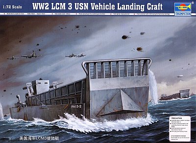
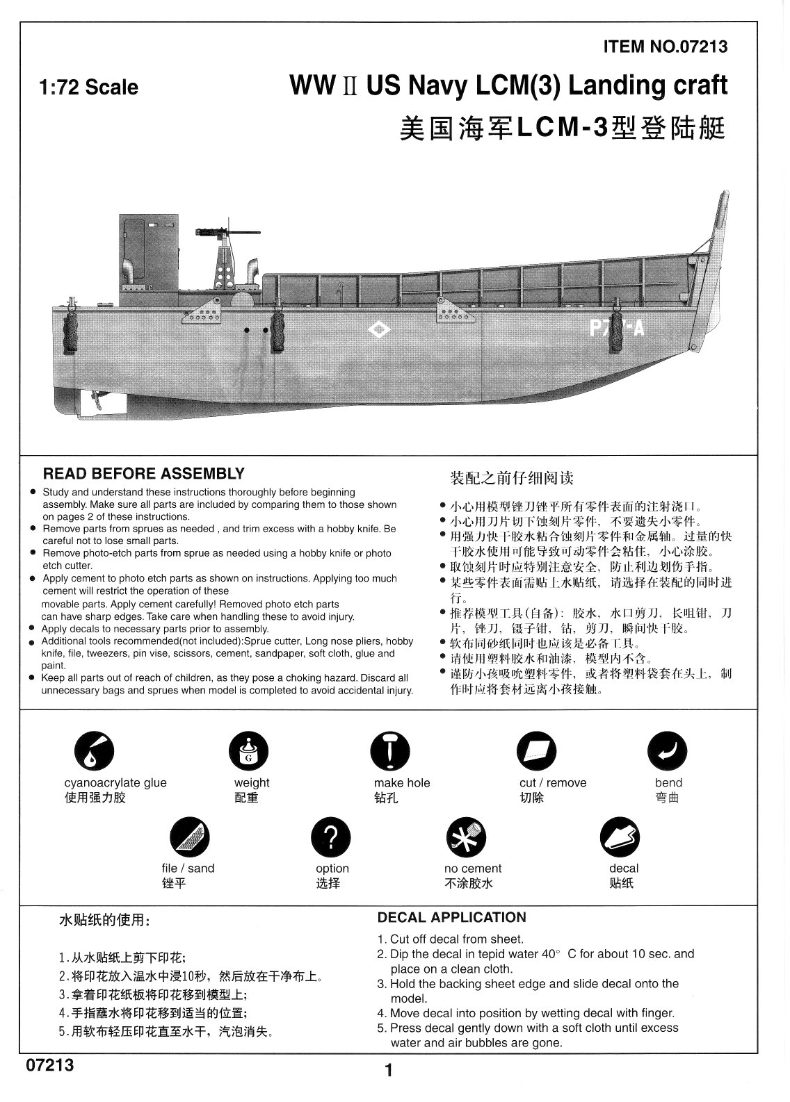
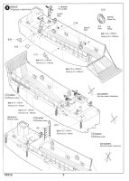
The Kit
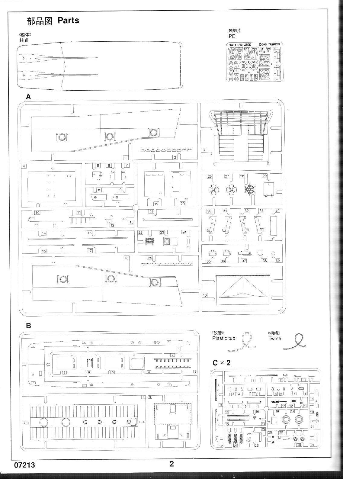
What you get in the box is a set of four sprues containing 139 parts plus a beautiful single piece hull, all moulded in a medium-hard, light gray coloured plastic.
There is also a short length of plastic tube, a piece of string, a photo-etched fret with 26 parts and a decal sheet. Almost all of the parts have noticeable seams
and in some cases there was a bit of flash. Detail is excellent throughout. Instructions are in an 8 page 7.5" by 10.25" booklet. Construction sequence is outlined as
9 separate steps in exploded diagram format.
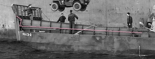
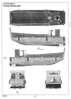
The painting guide has only a single camouflage option, P77-A in D-Day livery from the transport USS Thurston (AP-77), but on the decal sheet there markings for
another craft, PA13-2 from the USS Joseph T. Dickman. I always try to find corroborating photos for my builds if possible, and though my web searches turned up no pictures of P77-A,
I did find one for PA13-2, which clinched my decision as to which boat to build.
There is one oddity with the kit. The instructions gives alternate construction options for Royal Navy boats, but there are no decals for them nor painting
instructions. So I ignored all the RN options and removed the RN parts from the sprues. I also removed the parts for the German beach obstacles.
Construction
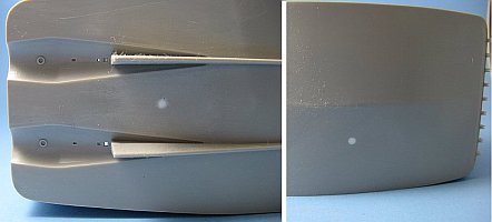 |
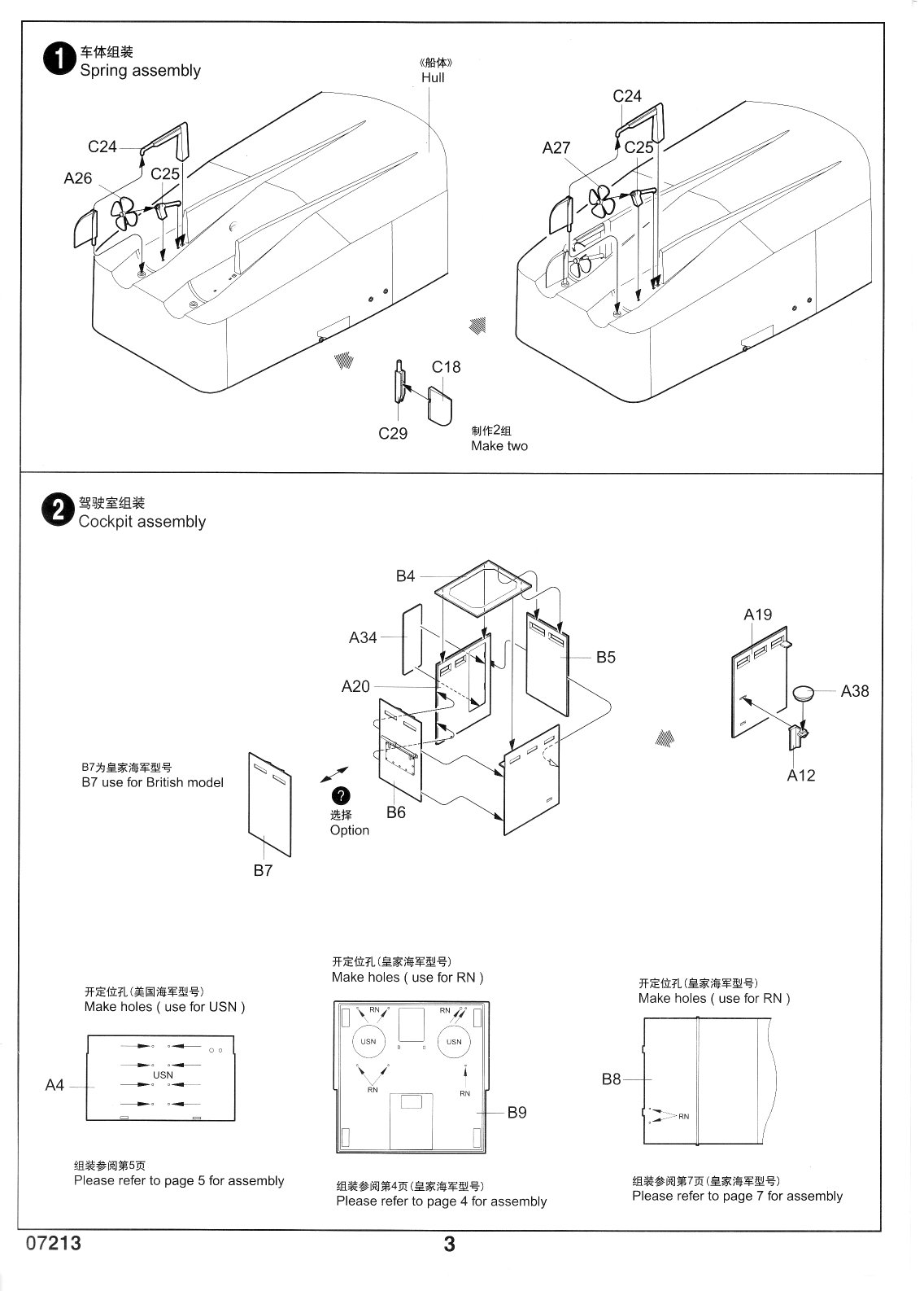
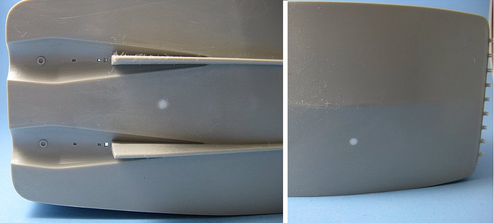
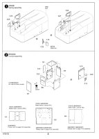
First I started by filling the two large holes on the hull bottom, then I moved to Step 2, building the wheel house. Here there are some major ejector pin
sink marks on the inside surfaces of the walls which were filled. I left the door off because almost every LCM(3) picture I found showed it removed. There
is a hole in the port wall to attach the fire extinguisher that I filled because my reference picture did not show the extinguisher there. Some of the vision
slots have flash that needs to be removed. A test fit revealed that the built wheel house would not fit over the raised hump assigned for it on the deck so some
scraping and sanding was needed to thin the walls, and I also trimmed some plastic from the hump's sides. The wheel house was left off to be painted separately.
|
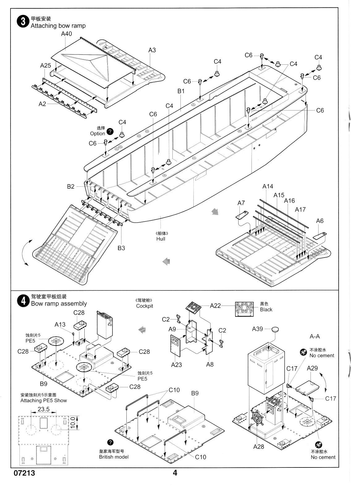
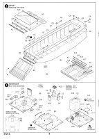
Then I built the cargo bay as per Step 5 and moved on to a combination of Steps 3 and 6 so I could test the fit of the hull with the cargo bay and the ramp hinge.
The ramp was built as per the instructions and the deck was glued in place. The seam running along the join line between deck and hull was filled. The filling
destroyed the moulded on weld seams. These were repaired with thin plastic sheet and roughed up to match the kit's welds. I though it rather odd that the weld
beads just stopped at the bottom edge of the hull so I added more welds, spanning from side-to-side under the hull.
I played around trying to get the ramp to close properly against the hull with the two hinge pieces in place, but it was a no go. To get an acceptable fit I
finally trimmed some of the length from the upper hinge. I added some plastic spacers between the vertical part of the hull and ramp to remove a see through.
Trumpeter gives you two options for bumper cleats and for PA13-2 I needed parts C6.
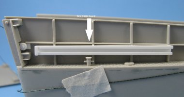 |
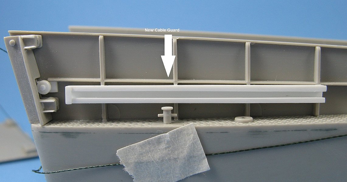
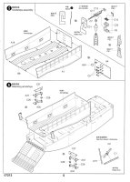
Before I could add the ramp pulleys I had to make some modifications. First I scrapped the kit's equalizing sheave/cable guard and built a replacement from plastic sheet.
The slide inside the sheave came from a Heller LCVP. |
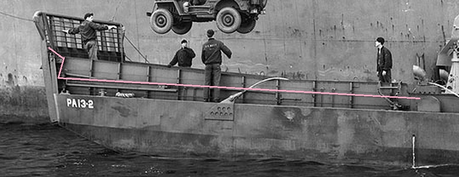
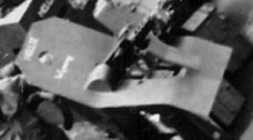
(Incorrect kit cable routing)
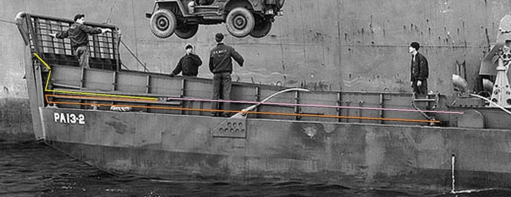
(Proper cable routing) |
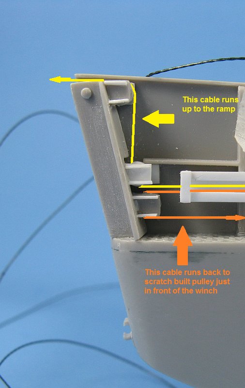
The instructions have the winch and cable routing incorrect, with two winches, one per side, each with cable running forward to the ramp. My references showed
only a single winch on the port side with a different method for routing the cable. The cable should run from the winch to the cable guard/equalizing sheave. At
the sheave the cable splits, with one cable running through a pair of pulleys up to the port side of the ramp. The other cable runs through another pulley that
sends it to the stern of the boat, where it goes around a pulley just in front of the winch, passing through the hull to the starboard side to yet another pulley,
and then forward to a pair of pulleys, and thence up to the ramp. |
Port side changes for correct cable routing
Starboard side for correct cable routing |
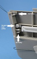
To match my references I had to make more pulleys. The starboard pulley structure was built and glued in place as per the instructions, and the starboard
winch was deleted and its mounting point shaved from the deck. The port side pulley
structure needed to have an extra pulley, which I made from plastic sheet and rod. Two additional pulleys were also fashioned and glued in place and holes
drilled in the hull. I then routed the fishing line through the two holes drilled in the hull.
|
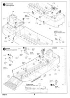
Returning to Step 4, I built the steering wheel console and added the remaining parts to the wheel house deck. Test fitting of the console to its mounting point showed
the same tight fit experienced previously with the wheel house, so the console walls were scraped and the sides of the hump it mounts over were trimmed. The console
was left off to be painted separately. The hinges for the fore access hatch (parts C17) are too tall so they were shortened to allow the hatch to sit level. I also drilled two
small holes at the center point on the deck where the gun bases were supposed to mount. There was a gap between the bulkhead and the upper deck that was filled with
a section of square rod, and then the raised deck was glued to the hull.
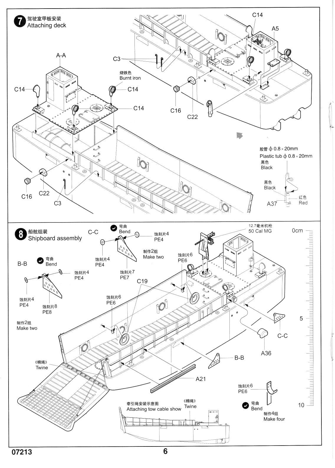
Steps 7 and 8 were next. I followed them as outline except I didn't add the fire extinguisher or the life preserver rings and their photo-etched mounts.
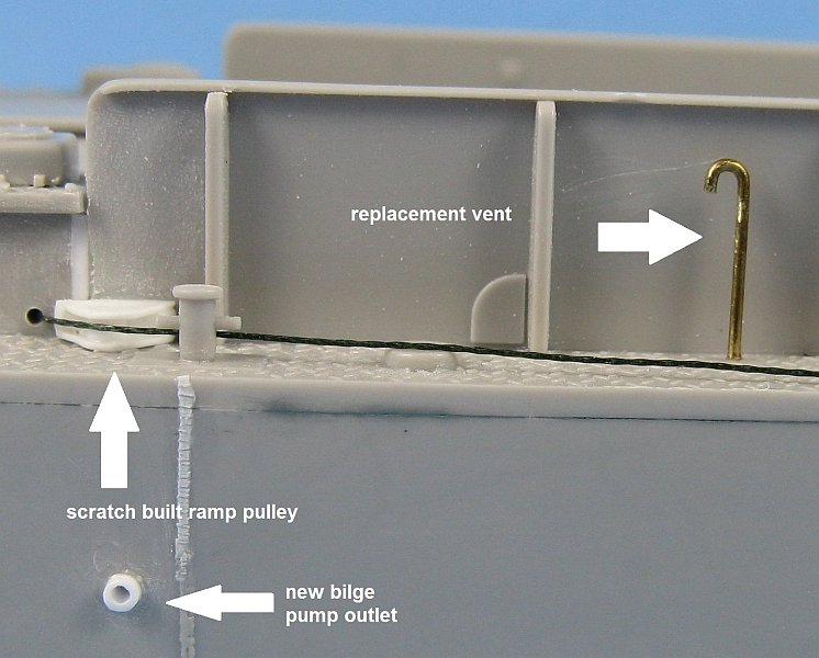
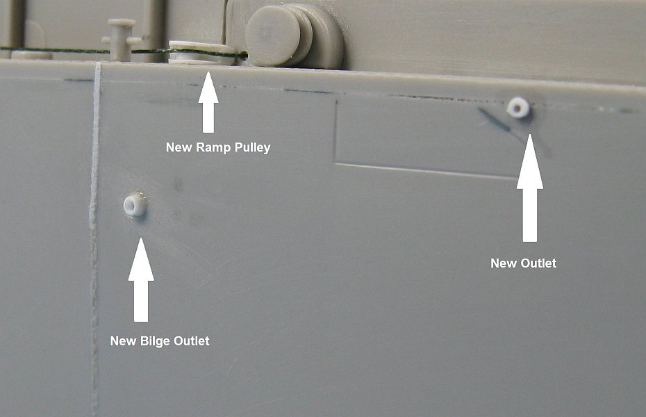
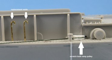
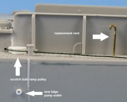
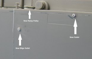
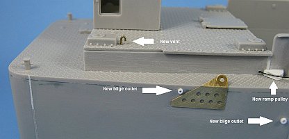
I replaced the four candy cane shaped vents (2 on port gunwale, 1 on the starboard gunwale & 1 on the wheel house deck) with stronger replacements bent out of brass wire. At this
point I realized the kit's ventilators didn't exactly match my reference picture. Figuring it was too difficult to make new ones I settled on drilling out the kit parts. I removed the incorrectly placed bilge outlets and added new ones placed according to my reference pictures. Also added was engine exhaust pipes and some scratch built covers.
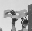
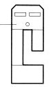
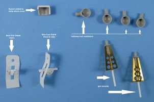
Two views of the correct shield |
Incorrect Trumpeter shield |
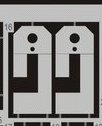
Incorrect Eduard photo-etched shield |
At this point I put together the stands for the .50cal machine guns, but did not attach the guns as my reference picture showed the boat without them. I attached a
short section of plastic rod to the bottom of their bases to act as both a hand hold for painting and as a locating pin to fit into the holes I had previously
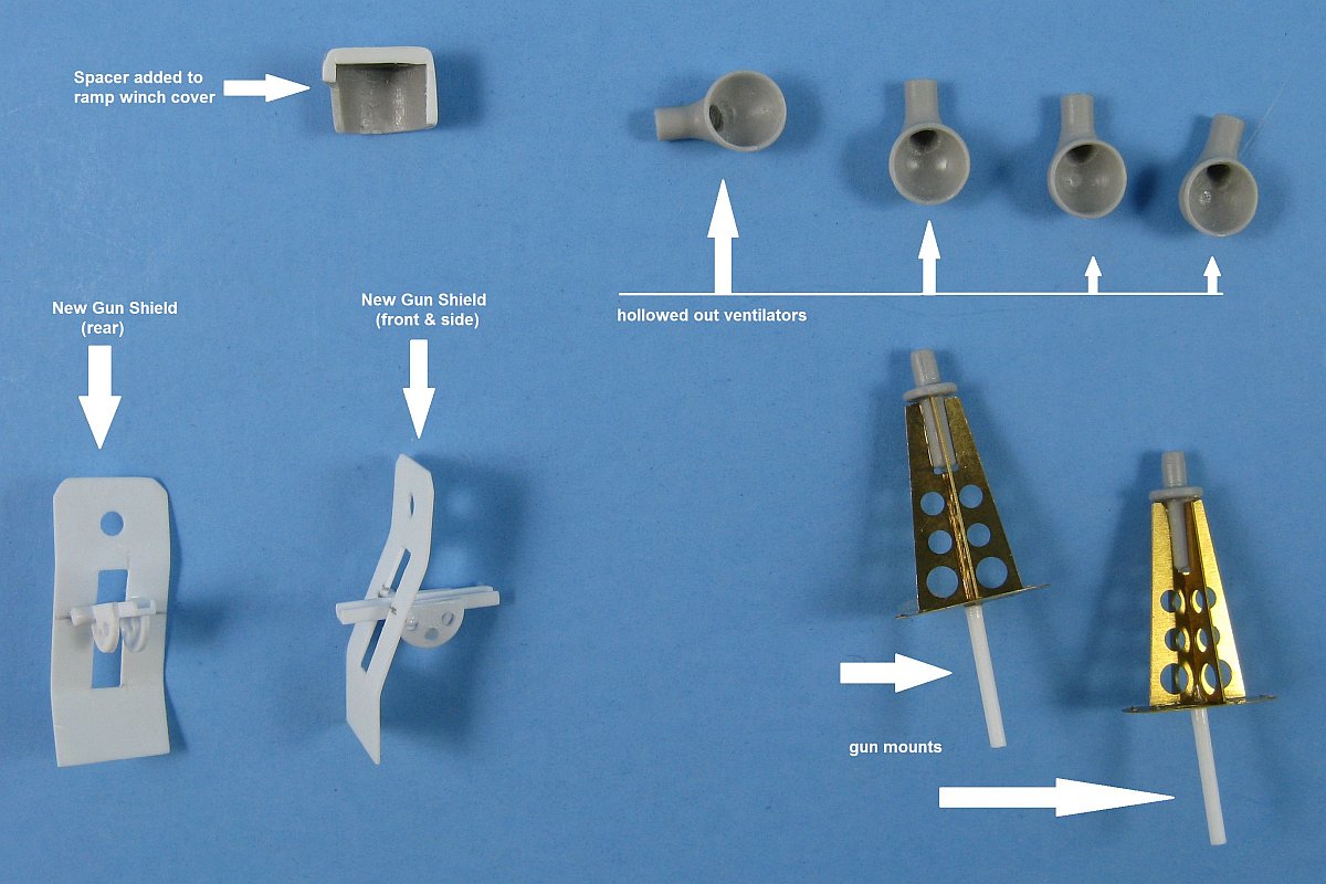
drilled in the raised deck. The kit's shields are beautiful photo-etched parts - but are completely wrong. Even the Eduard aftermarket set is incorrect. The
shield should have a single circular vision hole, not twin rectangular slots, and the shield should be solid and not have the small section removed from it. also
note that the gun barrel passes through the large slot in the shield and not through the tiny circular opening found on both the Trumpeter & the Eduard replacement
shield. Since both the kit and aftermarket shield were found wanting, I made my own shields from plastic sheet, using the kit versions as a template, and fashioned
new gun mounts.
|
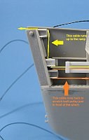
With the hull now complete and the ramp in place I routed the fishing line around the pulleys to the ramp. First I ran some fishing line from the winch to the
slider in the cable guard. A moment of panic set in when I couldn't get the line routed around the ramp pulleys. This wasn't what happened when I tested everything
earlier. After some thought I realized that the problem was caused by the ramp blocking my ability to loop the cable back around the pulley and the solution came
in the form of my dental pick. With this I could just reach inside and snag the cable allowing me to pull it through the hole and around the pulley. So take heed -
do not add the ramp until you've routed the cable! All the cable's contact points got a dab of cyano glue to hold everything in place.
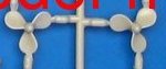
Italeri 1/35 scale prop |
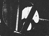
Wide chord blade prop
from Reference [4]. |
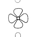
Trumpeter 4-blade
wide chord prop |
As for the props, there is some question as to their accuracy. The Italeri kit has a three bladed fairly narrow chord prop. The next
picture shows a wide chord prop that has three wide chord blades and the third picture shows the Trumpeter prop, with four wide chord blades. Based on what I found,
it looks that the Trumpeter kit prop is not correct, but not wanting to spend a lot of time converting the kit props, and without any definitive proof on the
correctness of the Trumpeter props, I chose to just go with the kit props. Note that the props are handed so keep track of which prop goes to which shaft. |
 |
The final parts were some scratch built items not included with the kit. These were:
- pyramid mast above the wheel house
- manual bilge pump
- life preserver ring mount to the port side of the wheel house
- wire loops that attach to the top of the gunwales
- braces for the skegs
- U-shaped cleats just aft of the ramp
|
Painting & Decaling
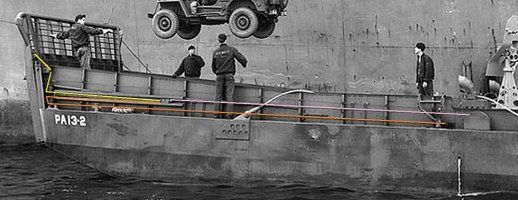
Based on the black and white pictures of PA13-2 as well as colour photos of other LCMs, the model received a blue over black scheme. After a light grey primer,
I sprayed a pre-shade in Testors Flat Sea Blue (1718) along panel lines and inside recesses. Next, cloud patterns of Testors Intermediate Blue (1720) and Testors
Navy Blue Grey (2055) were built up allowing some of the dark Sea Blue to show through, followed with some additional cloud pattern spraying with Intermediate Blue
lightened with flat white. Some rust stains were added and a dry brushing with Flat Sea Blue and Intermediate Blue reduced the contrast between the colours.
For the black lower hull, I masked the uppers and then sprayed a coat of Floquil Engine Black followed with highlighting and streaking with the black lightened with
some Testors Dark Earth Brown (2054). Then a rust line on the hull was sprayed with the Dark Earth Brown. Using some flat black and a brush with stiff bristles I
vertically streaked the water line rust stain. Additional rust streaking was added to the bilge outlets and to various spots on the hull and to the lower edges of
the hull.
All the markings came from the kit's decal sheet. These were applied over some Testors Glosscote sprayed directly from the can, and Microsol got the decals to
sit nice and tight. All the sub-assemblies were glued to the boat and a flat coat finished was sprayed.
Final Touches
As I did on my LCVP build I used a set of woven bumpers from Thachweave Products located in London, ON. These are a vast improvement over those supplied by
Trumpeter.
With a steady hand I placed a drop of 1-minute epoxy using the tip of a round toothpick on each instrument dial to give it a more realistic appearance.
One of the big disappointments with the kit is a lack of display stands which forced me to make my own from some styrene plastic rod and sheet. These were
painted gloss black and attached to a wood base with epoxy.
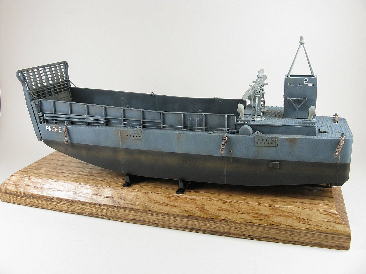
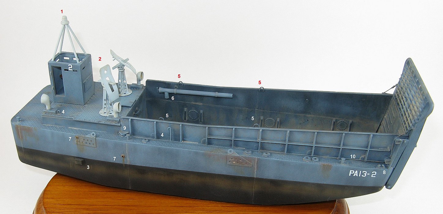
| Changes overview - starboard |
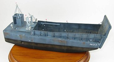 |
- scratch built mast
- scratch built gun mounts
- scratch built engine exhaust outlet
- replacement vents
- wire loops
- scratch built manual bilge pump
- new bilge pump outlets
- scratch built cleat
- scratch built ramp pulley
- re-routed ramp cable
|
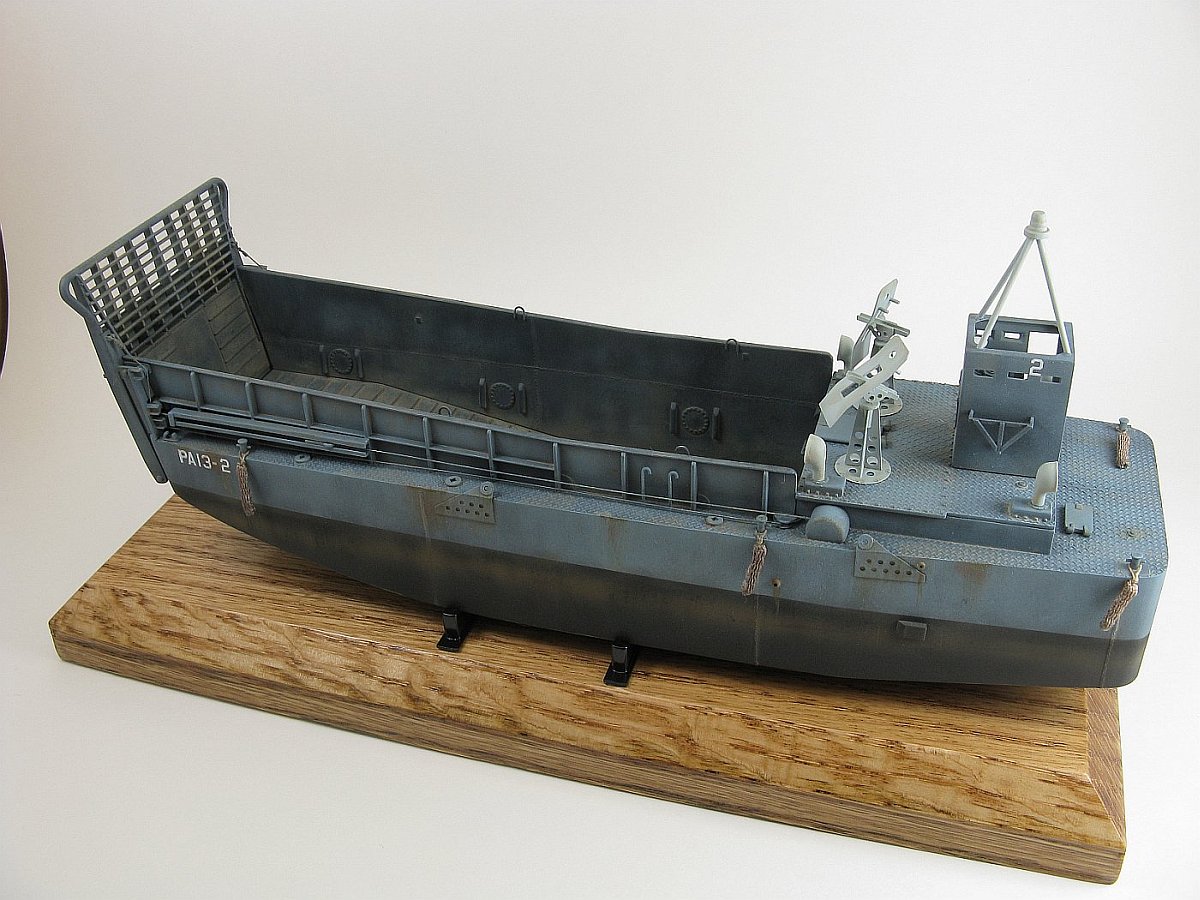
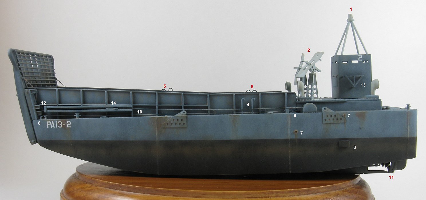
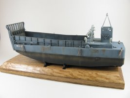
| Changes overview - port |
 |
1. scratch built mast
2. scratch built gun mounts
3. scratch built engine exhaust outlet
4. replacement vents
5. wire loops
7. new bilge pump outlets
8. scratch built cleat
9. scratch built ramp pulley
10. rerouted ramp cable
11. skeg braces
12. scratch built ramp pulley
13. scratch built life ring holder
14. new scratch built cable guard & an equalizer from Airfix LCVP
|
References
[1] US Landing Ships in Action, Squadron Signal Publications, Carrollton 2003 ISBN-10: 0897474511 ISBN-13: 978-0897474511
[2] various web reviews and pictures of the 1/35 scale Italeri LCVP kit
[3] Naval History & Heritage Command site
[4] Skill in the Surf: A Landing Boat Manual.
Review sample purchased by the author.


|