|
sWS (schwerer Wehrmachtschlepper) |
|||
| Kit # 7201 | Construction review by Rob Haelterman - heman_148(at)hotmail.com | |||
|
sWS (schwerer Wehrmachtschlepper) |
|||
| Kit # 7201 | Construction review by Rob Haelterman - heman_148(at)hotmail.com | |||
  |
History
The kit
Construction
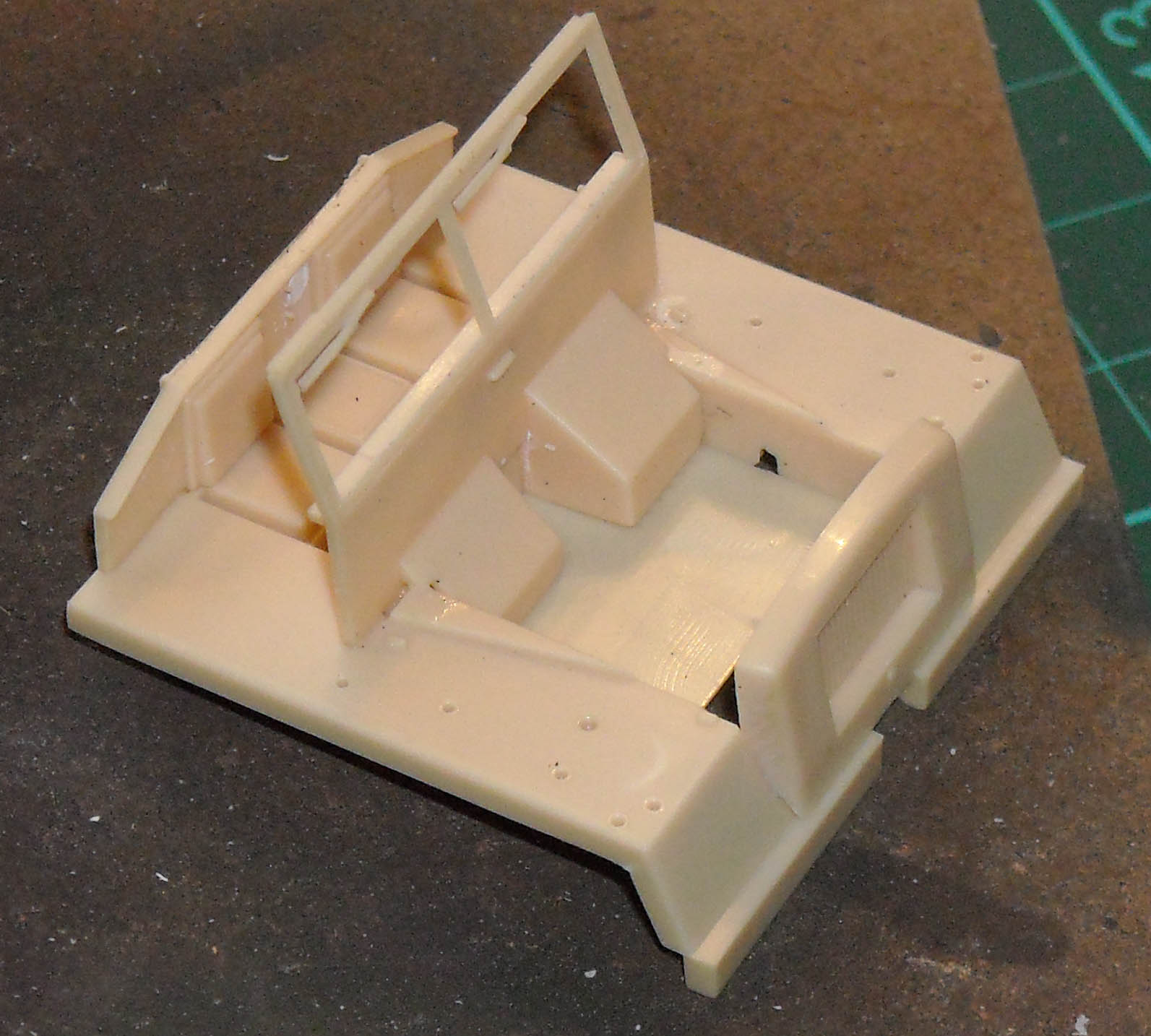
As the construction sequence results
in easily handled sub-assemblies I decided to jump to the assembly
of the cabin. The locating pegs help here, but with my limited skills
the assembly resulted in a notable gap between part 34 (the one with
windshield and dashboard) and the bonnet, as part 34 was about 0.5mm
too far to the rear to fit well. Next time I would change my assembly
sequence by starting from the nose and moving backwards and ignoring
the locater pegs for part 34, instead of adding the bonnet last. The
way I did it also resulted in some minor gaps between the bonnet,
radiator and the mudflaps. While nothing really hard to remedy, it
again took more time than the rest of the construction combined. Once
again, there are also some ejector marks on the inside of the cabin.
On the plus side, the kit is engineered in a way that makes opening
up the bonnet fairly straightforward. A 'transparent' windshield is
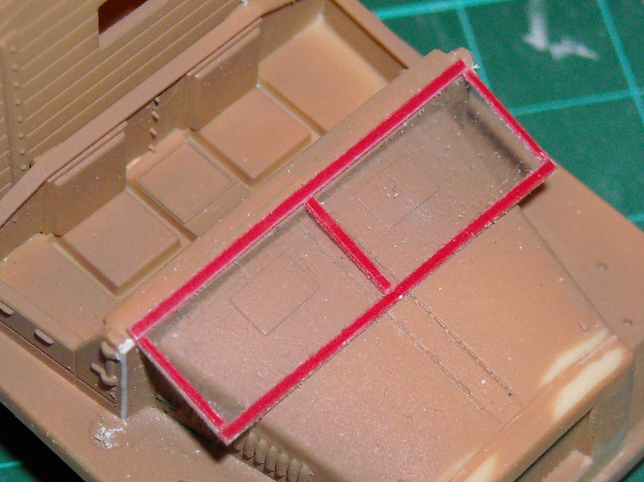
not provided, so you will need some clear acetate to fill the window
frames later. For the vehicle I was building I needed the windshield
to be folded down. I first envisaged using the kit part for that,
but I messed this one up quite badly, so I resorted to scratchbuilding,
which actually made life easier, as I now could build the frame onto
the transparency, instead of trying to insert transparencies into
the frame. I used red (!) Dymo tape for that, but should have remembered
that I had black tape in one of my drawers. Any scratches in the paintwork
would have been so much less of a problem if I had...
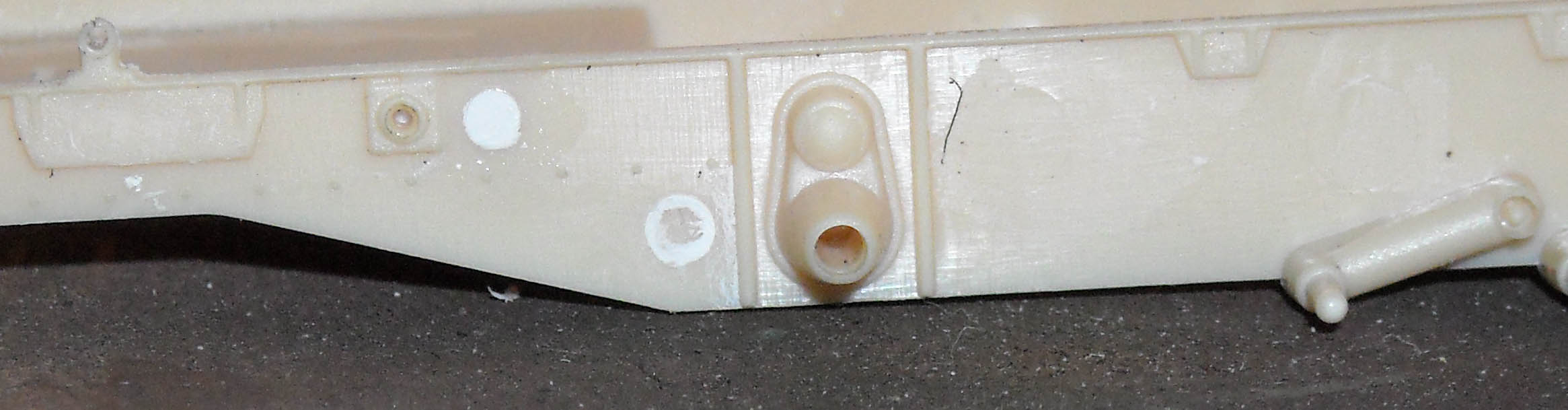
At this point I was working on three
subassemblies: lower hull, cab and cargo bed. Turning my attention
back to the lower hull, I basically followed the instructions but
made a small improvement by drilling out the end of the muffler. Apart
from the running gear, I completed the assembly of the lower hull,
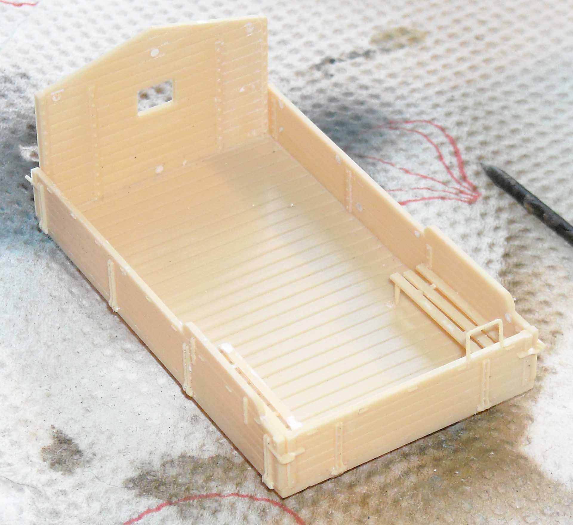
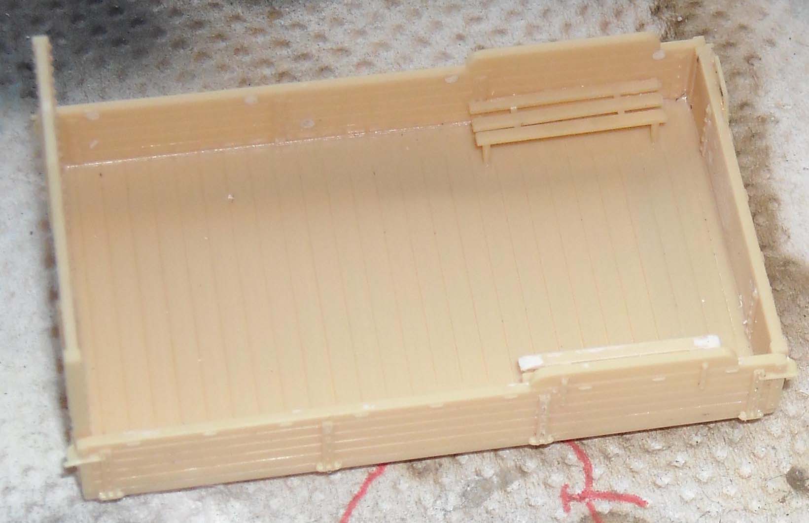
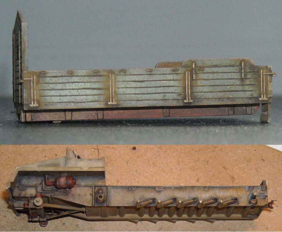
before joining the subassemblies. Again hopping forward in the manual, I tackled the cargo bed next. Numerous ejector marks need to be cleaned up, but due to the nature of the parts, that's a quick job. I guess the three depressions on the bottom of the flatbed are to be drilled out for the Flak-carrying version (kit 72006), so I filled them in for my vehicle. Also, there is a part (58) on the sprues, which I guess alternates with part 45 at the front of the cargo compartment in the Flak version. A dry fit of the lower frame (part 43) with the cargo bed was so good that I felt I did not need to glue it, which really helps with painting the lower frame and tracks ! The finished vehicle is just that: a cargo bed, snapped onto the lower hull.
With the lower hull finished, except
for the running gear, I added the cab to it, minus windscreen, as
this would have to go on after painting. Piece 28 (which I was unable
to identify) was broken on the sprue, but easily repaired. It took
me a long time before I discovered piece 17 (which I believe is the
filler cap for the fuel tank). It was attached to the rear hull plate
(part 4) on the sprue, and as my brain was on a holiday during this
build, I had actually left it attached to the hull until after the
painting and weathering phase. If there is a weaker spot in the kit,
then it's the roadwheels, as they present some minor deficiencies
(most of which, after assembly, are hidden). The most annoying being
the uneven rim, which, among others, makes it more difficult to paint
the rubber tyres.
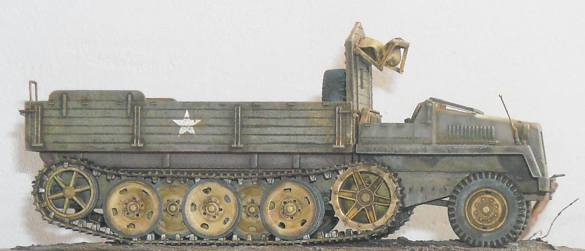
Tracks The first cause of trouble was my choice of assembling the tracks after the lower chassis was mated with the cab. (This assembly was already painted at this stage.) This is manageable, as this modus operandi only obstructs your access to the drive sprocket, and this can be fitted out with track links before you glue it to the hull. If, on the other hand, you want to correct something when the whole running gear is on the hull (as I had to do eventually) you are in trouble. My advice: follow the manual and do the tracks at the start of the build. Secondly, when doing the drive-sprockets I discovered that a track pad plus link came out just a tad longer than the distance between two teeth. Either I didn't insert the one into the other deep enough, or you need to give a gentle rub with some sandpaper to each connector. If you don't, you will run out of space or have a track assembly around the idler with a slightly larger radius (i.e. with some stand-off). Neither option is really pretty. That the track teeth are rather poorly endowed, doesn't do any good here either. Moreover, I always tend to feel that with my limited skills there is always an ever so gentle misalignment to be noticed with these individual links, which eventually made me decide to do "some minor fixing". This minor fixing resulted in some foul words to be uttered and the whole track assembly to be disassembled on one side. When re-assembling I chose to place the longest lengths (and not the individual links) around the idler and drive sprocket, which eliminated any problem I experienced before. The fact that these lengths are very flexible helps enormously. If I ever build the same kit again, I will wrap lengths around the idler and sprocket again (where misalignment is the most noticeable) and make longer section out of the individual links for the top and bottom run, which actually looks more natural as they now fall better on the roadwheels than the perfectly straight sections. Another inconvenience of the fact that a "track unit" is two pieces wide (pad + connector) lies in the fact that it is difficult to match the circumference of the running gear by a multiple of "track units". There is little margin for sag, so you might want to create some play by doing the idler last and moving it slightly forward or backward to create a good match. For the ham-fisted like me: you get about 10 spare links, so you have some margin for error.
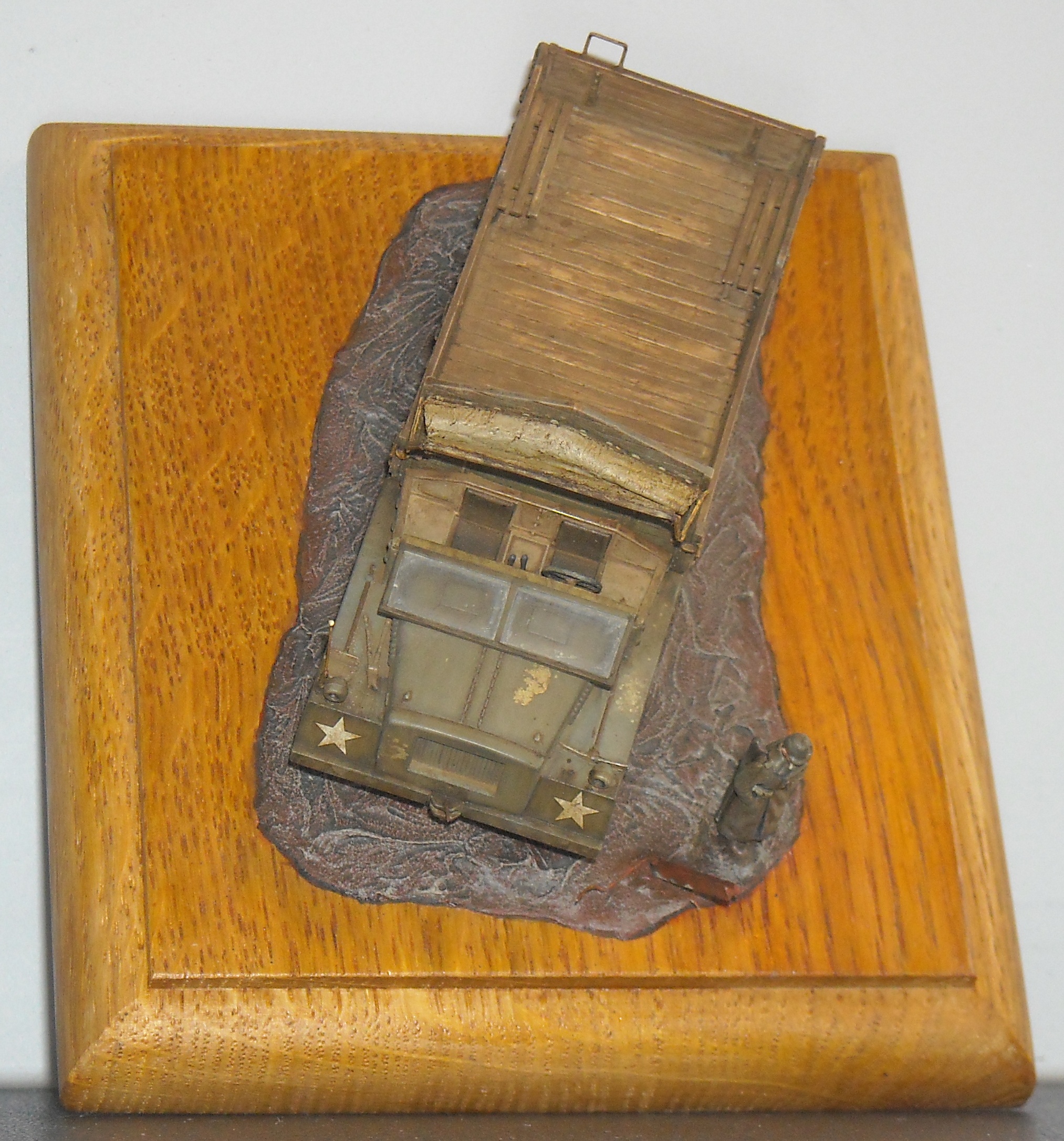
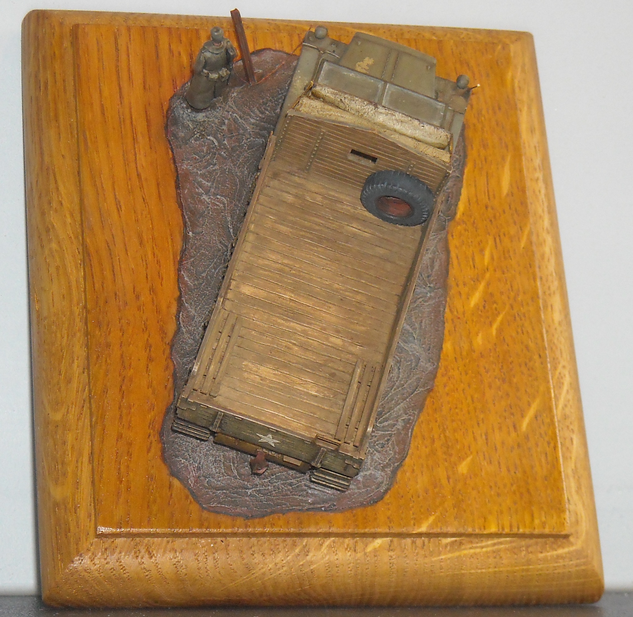
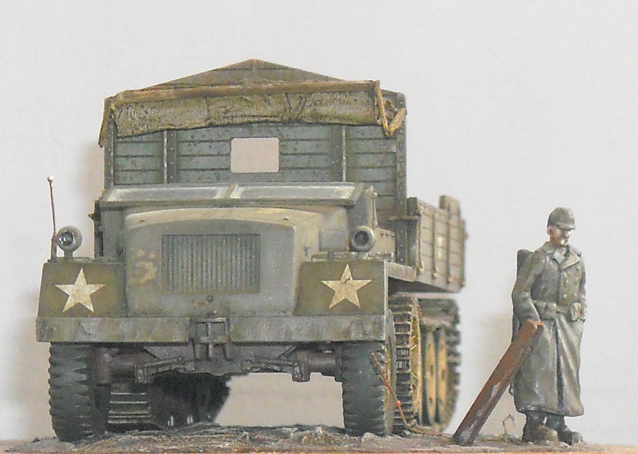
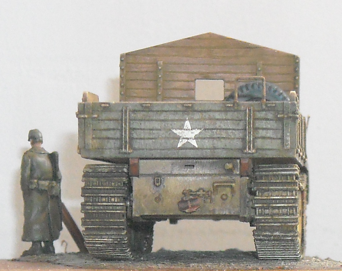
Final assembly The windscreen was added and a partially folded canvas for the cabin was made from paper towel, impregnated with white glue and some plasticard for the folding mechanism. Maco provides a canvas hood for the driver's compartment and the cargo bed (minus the sides), but I did not use those parts. While good, they might benefit from some extra creasing. I had a copy of the front wheels casted to be put in the cargo bed, as I wanted my model to correspond as closely as possible to the pictures I had at hand. A pin in the shape of an inverted 'L' was inserted in the front tow coupling. At the end of the build you are left with two Bosch headlights, an axe and a Notek light (or two in my case, as I left it off). Very nice additions for the spares box. The reason for this is that Maco has engineered the sprues in a way that you get two identical sprues on which some of the parts are only needed once, and that Maco has already included some parts for other variants of the sWS.
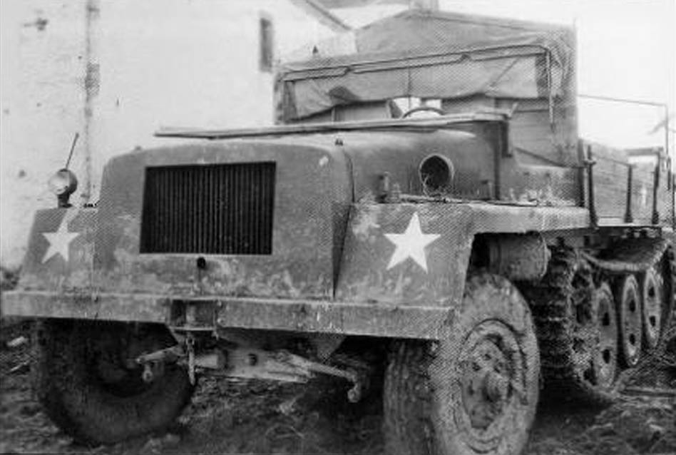
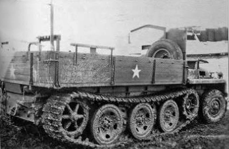
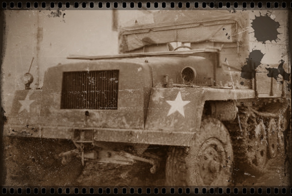
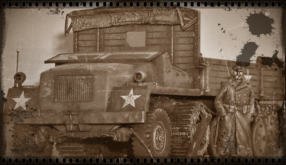
Painting and decals The decals are very thin and react very well to Set and Sol; they actually tend to slightly dissolve when using these products which makes any carrier film disappear. The only negative comment I have about the decals is that they show very slight striations in the stars, which is probably due to the printing process. The dissolving effect of Set and Sol and the oil washes I applied made these striations disappear. Vignette As I mentioned before, my specimen is absed on these two pictures.
References Other sources were http://en.wikipedia.org/wiki/Schwere_Wehrmachtschlepper http://wapedia.mobi/en/Schwere_Wehrmachtschlepper http://www.wwiivehicles.com/germany/half-tracks/sws.asp# http://www.geocities.com/pentagon/3620/sws.htm (which has now disappeared) |
| Back to Maco Kit List | Back to Home Page |
Article Last Updated: 17 April 2010 |
Back to Construction Review Page |


