MK72(MPK) |
Panzerjäger Marder II (Sd.Kfz.131) |
|||
Kit # 7208 |
Construction Review by Rob Haelterman - heman_148(at)hotmail(dot)com |
|||
MK72(MPK) |
Panzerjäger Marder II (Sd.Kfz.131) |
|||
Kit # 7208 |
Construction Review by Rob Haelterman - heman_148(at)hotmail(dot)com |
|||
|
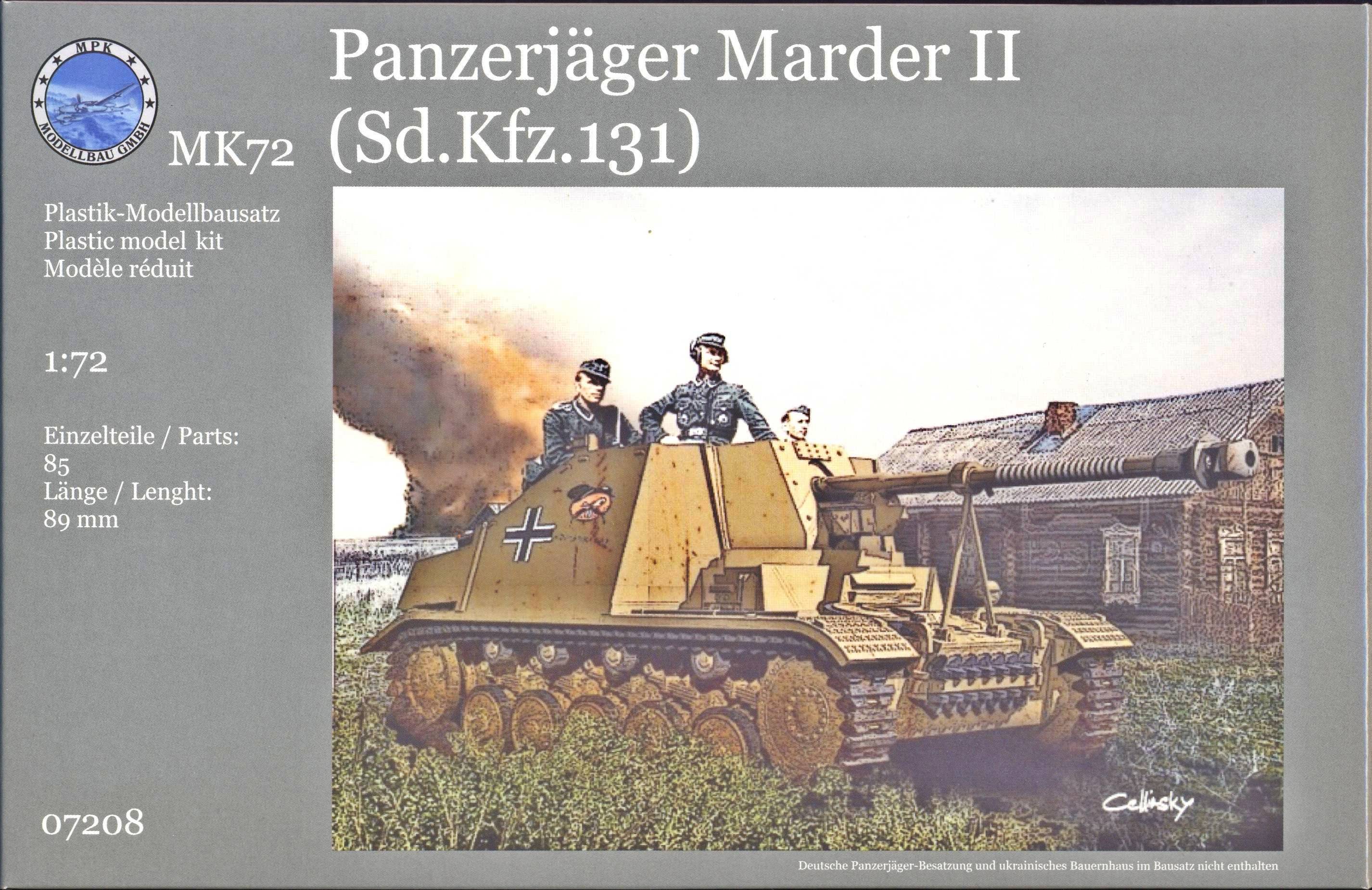
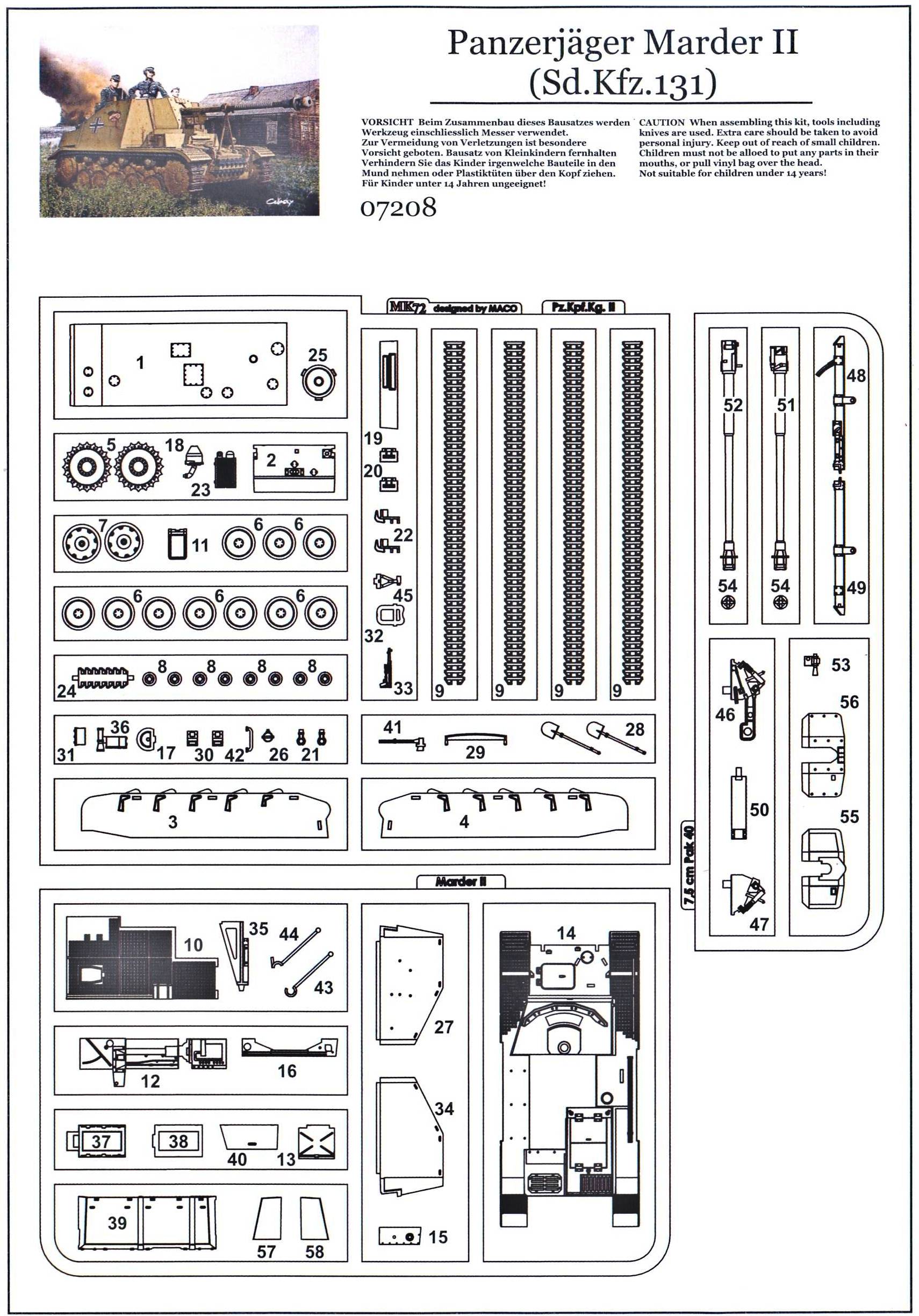
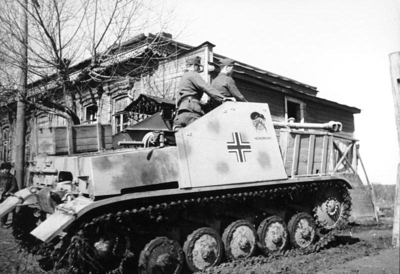
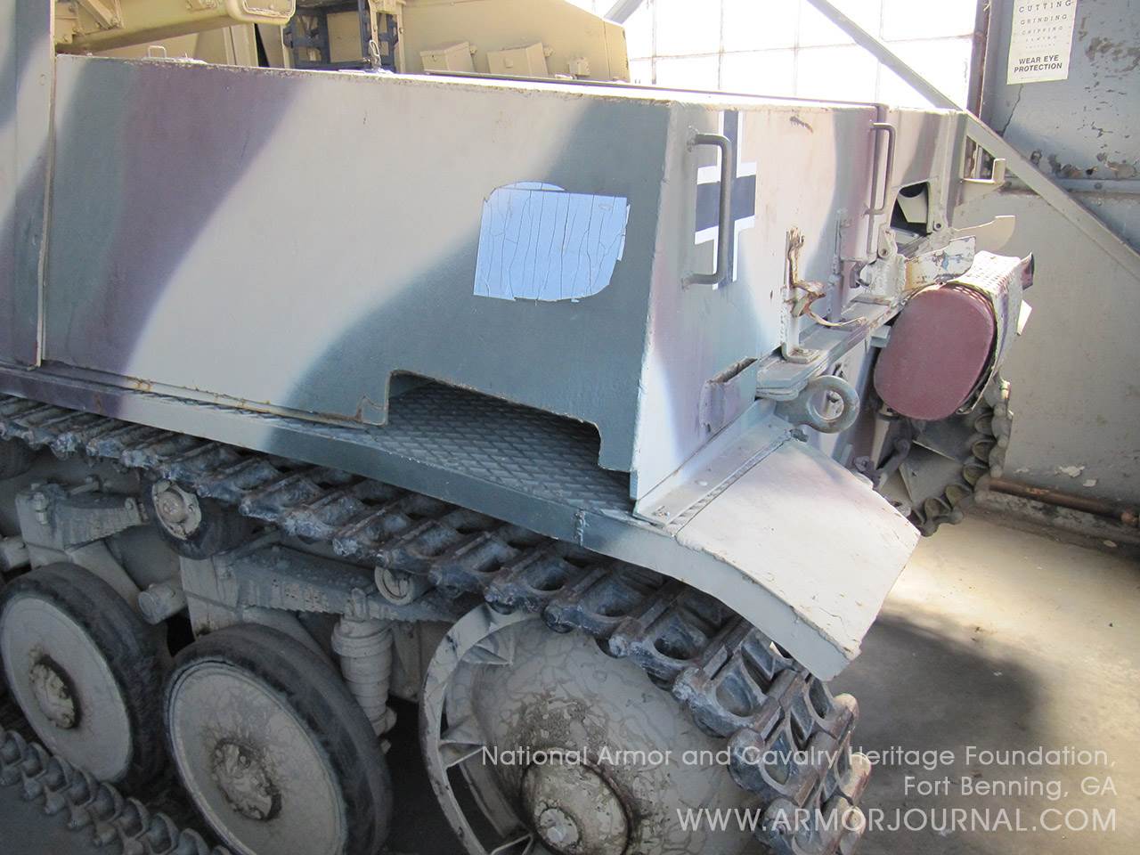
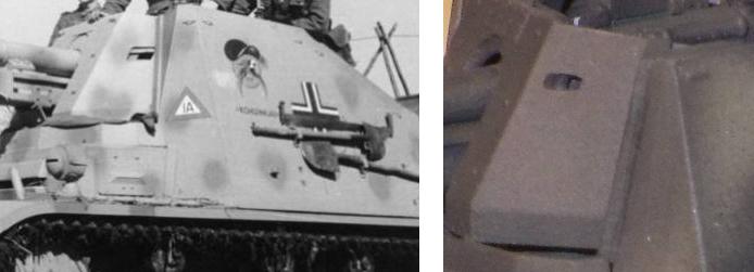
| History and version The Marder II (modeler's shorthand for Panzerjäger II für 7.5cm Pak 40/2 (Sd.Kfz.131)) was a German conversion of the Pz.Kpfw.II into an interim tank hunter. The first prototype was built in June 1942 and a month later the type went into production. Series production went on until March 1943, after which a small number were still being built by field workshops using obsolete Panzer II chassis (it seems Ausf. c.,A,B,C and F were used to this purpose). The latter had many visible differences and there even is one recorded example of a Marder II fitted with a 50mm gun. Most of the field conversions retained typical Panzer II features, like the fake driver's visor. [1]
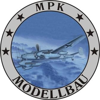
Phase I: gazing at the box and its contents This will be the second MK72 kit I build (previously, I built the Zugkraftwagen 1t (Sd.Kfz.10) Demag Typ "D7"), so I know what to expect: a fine kit. The backside of the box clearly shows the contents of the kit, so that "caveat emptor" hardly applies in this case. Notable features are the styrene "single length" tracks (like in the Demag), the double Pak shield and the gun barrel that is split length-wise.
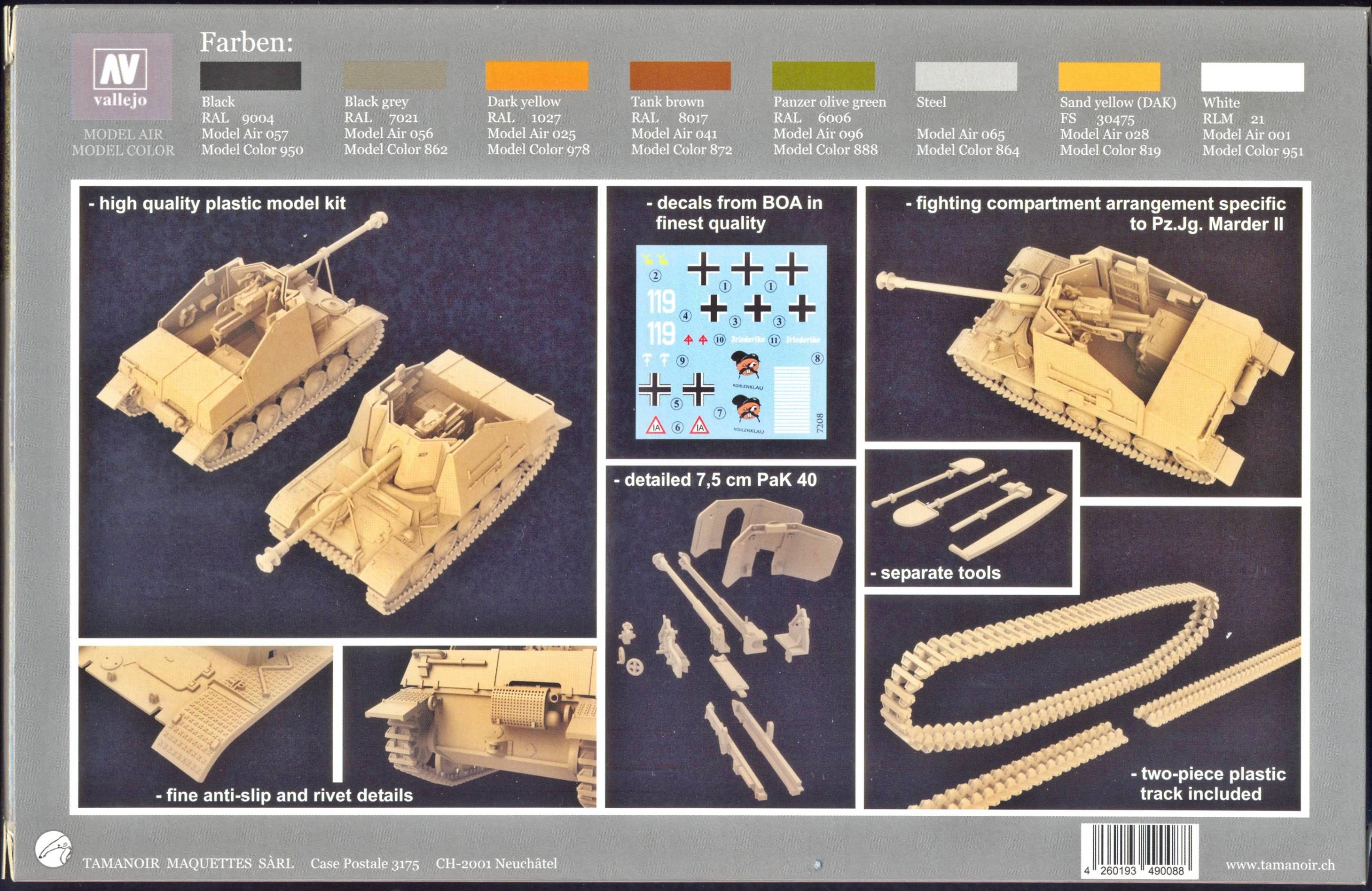
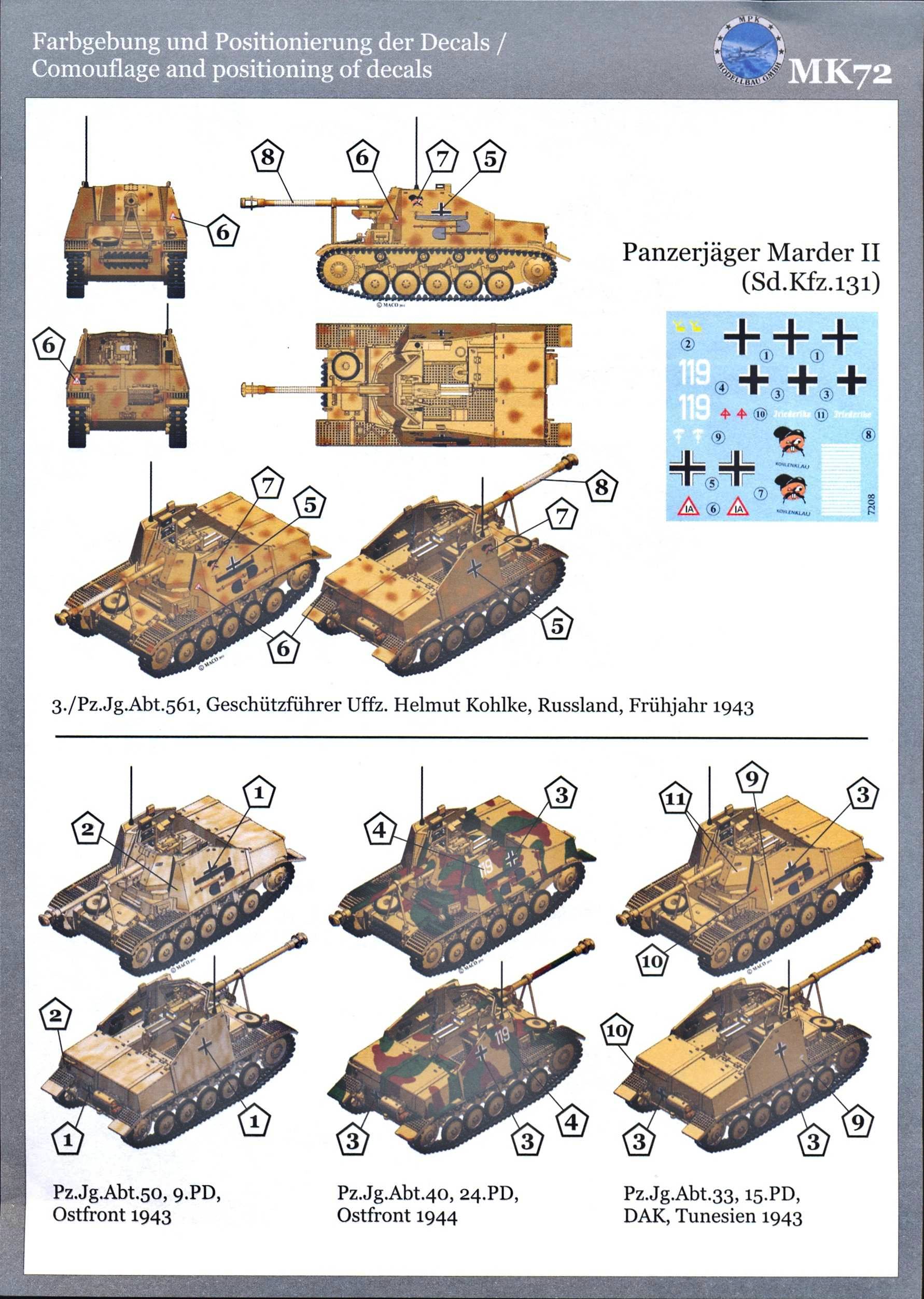
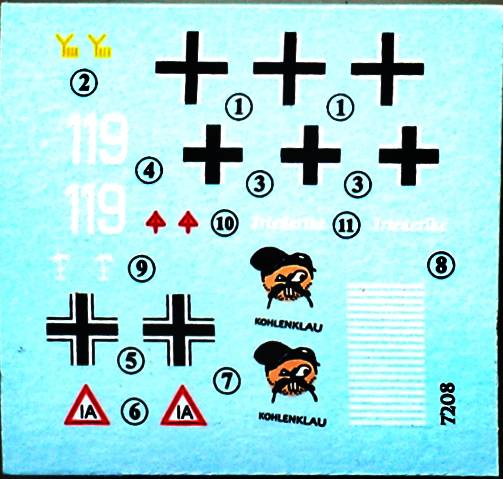
Marking options are provided for 4 vehicles, and MK72 offers a novel approach in that they don't use side-views, but three quarter views. One example even has a total of six views (and a painting on the boxtop). The four marking options on offer are: It's a pity that the color references are not on the sheet with the markings but on the back of the box, as the difference in printing makes it somewhat unclear what the colors are (at least to the non-initiated). In particular, the dark yellow and sand brown are difficult to tell apart. The decals look very good on the sheet.
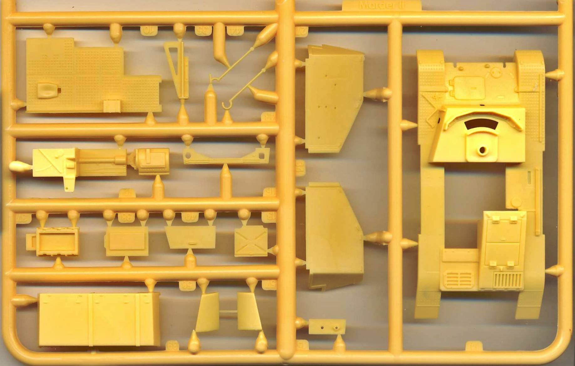
Looking at the sprues, it is clear
that it is likely that other declinations of this kit will be forthcoming.
Indeed, the parts that are common to the Panzer II and Marder II are
on one sprue and the parts that are typical for the Marder II on another.
The Pak40 is on one end of the common sprue, but you can see that
these are actually two sprues joined together, and labeled separately. Very little to no flash can be found, and the parts are very crisp. In more than one way they remind me of what Revell offers us these days.
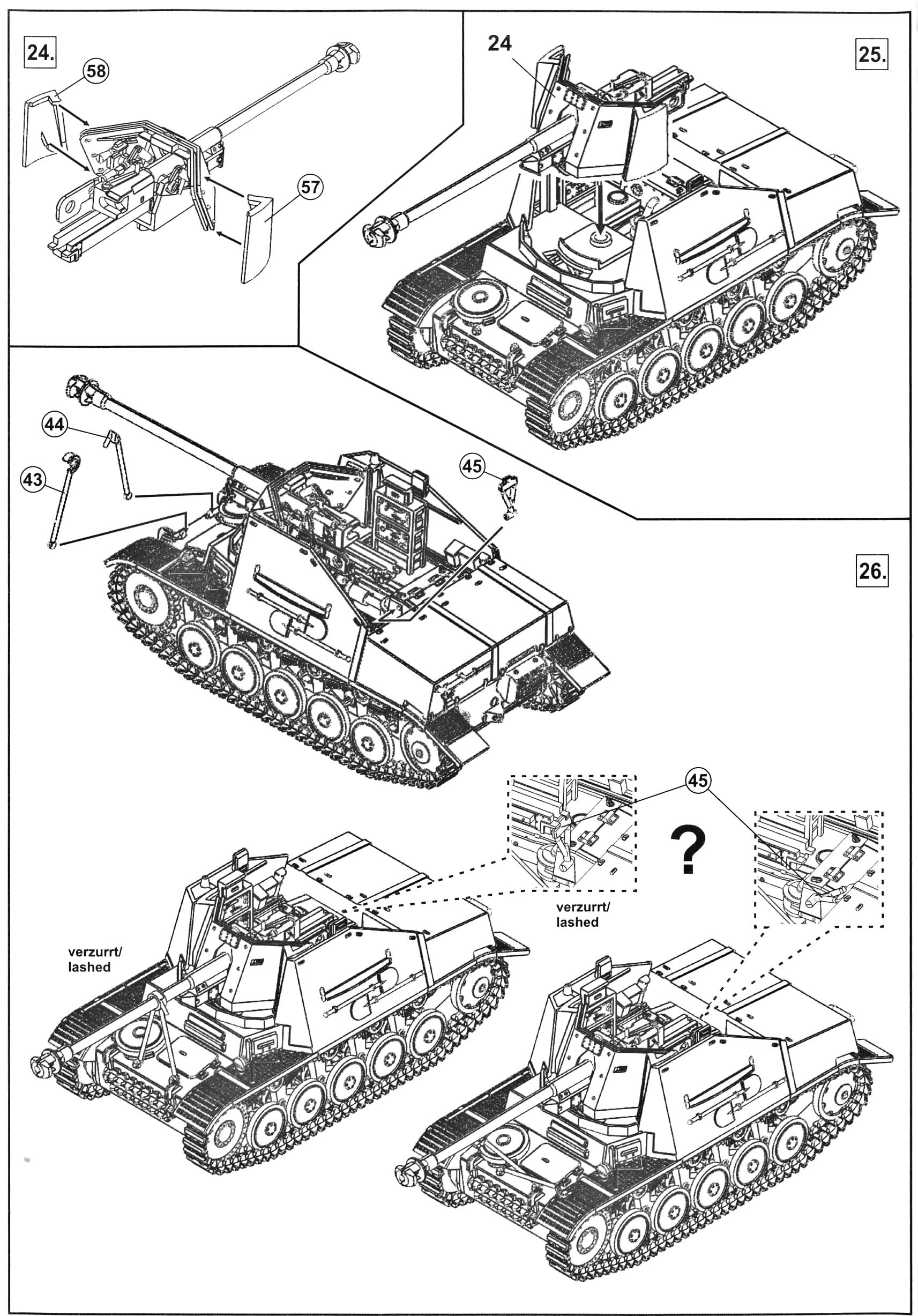
The manual is of the "common type", and presents no difficulties at first sight. The modeler will have the option to build the kit with the gun in traveling position or in firing mode.
Phase II: Assembly of major components Although I had promised myself to finish
the kits that already were on my workbench, I couldn't resist removing
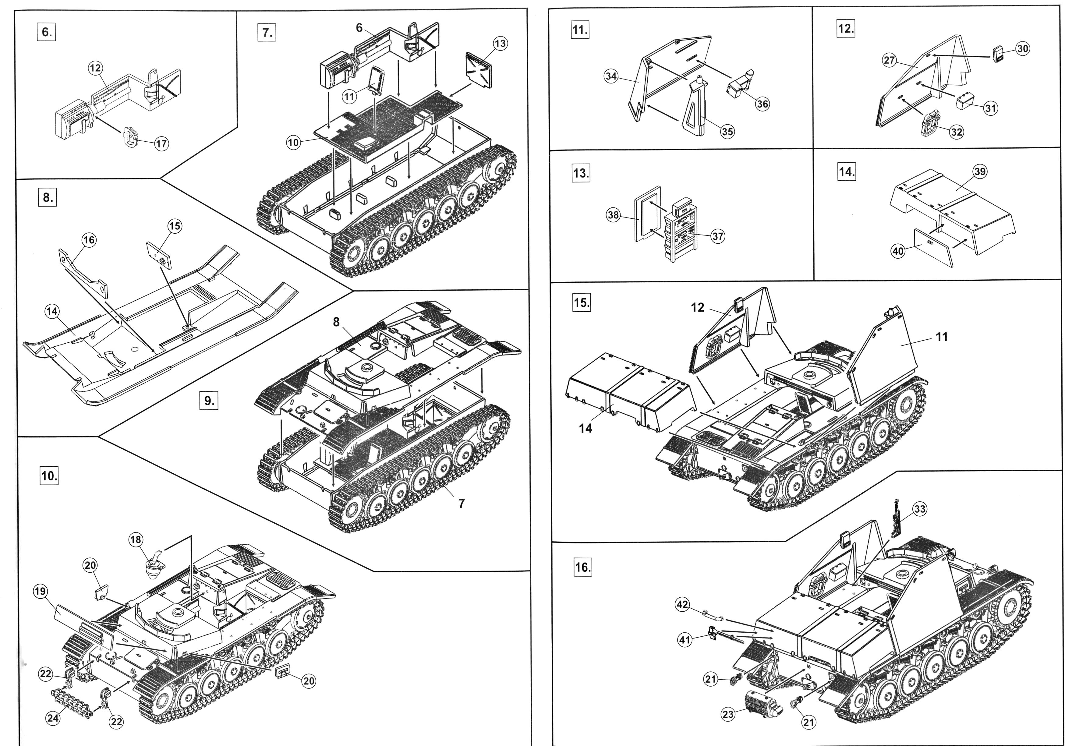
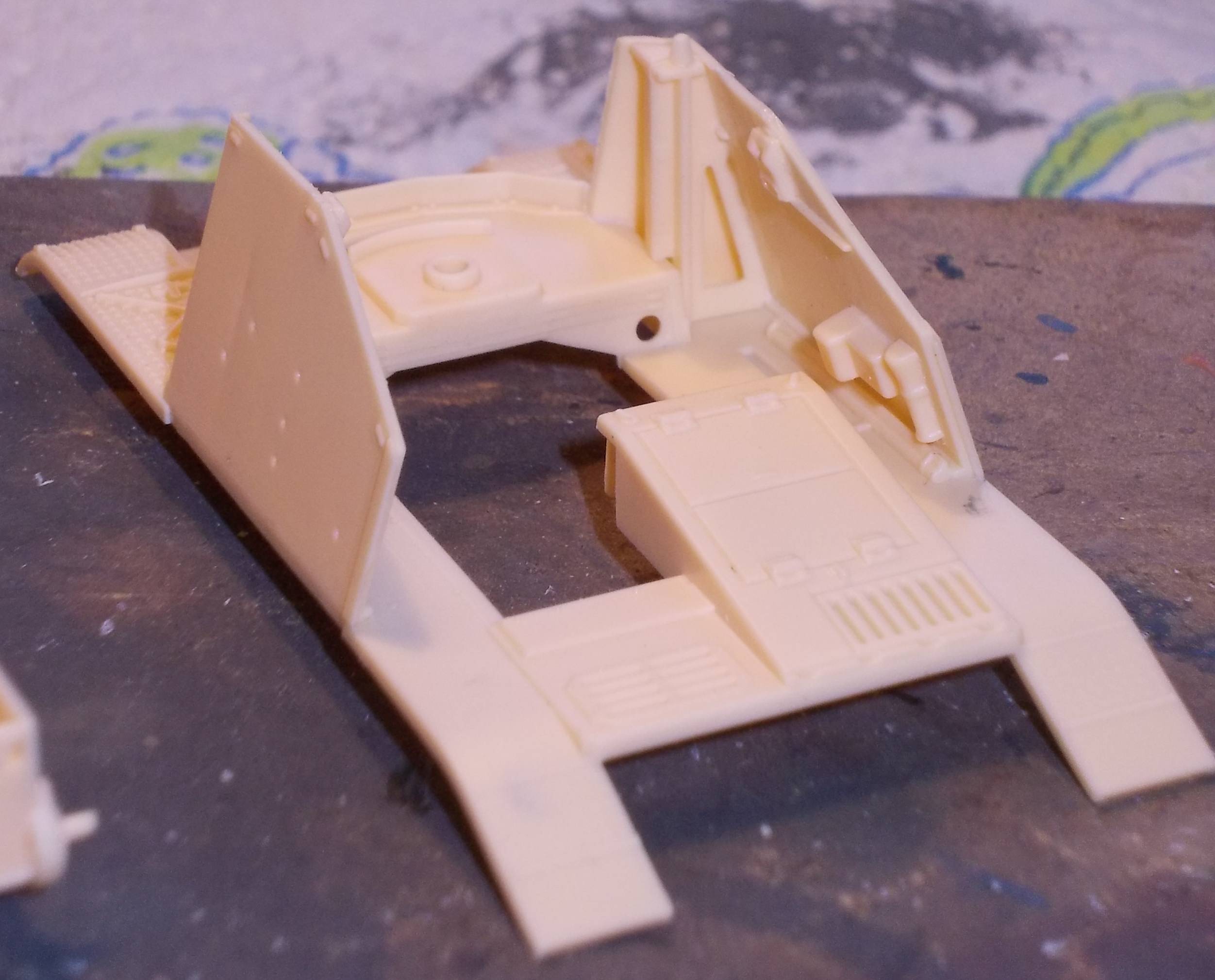
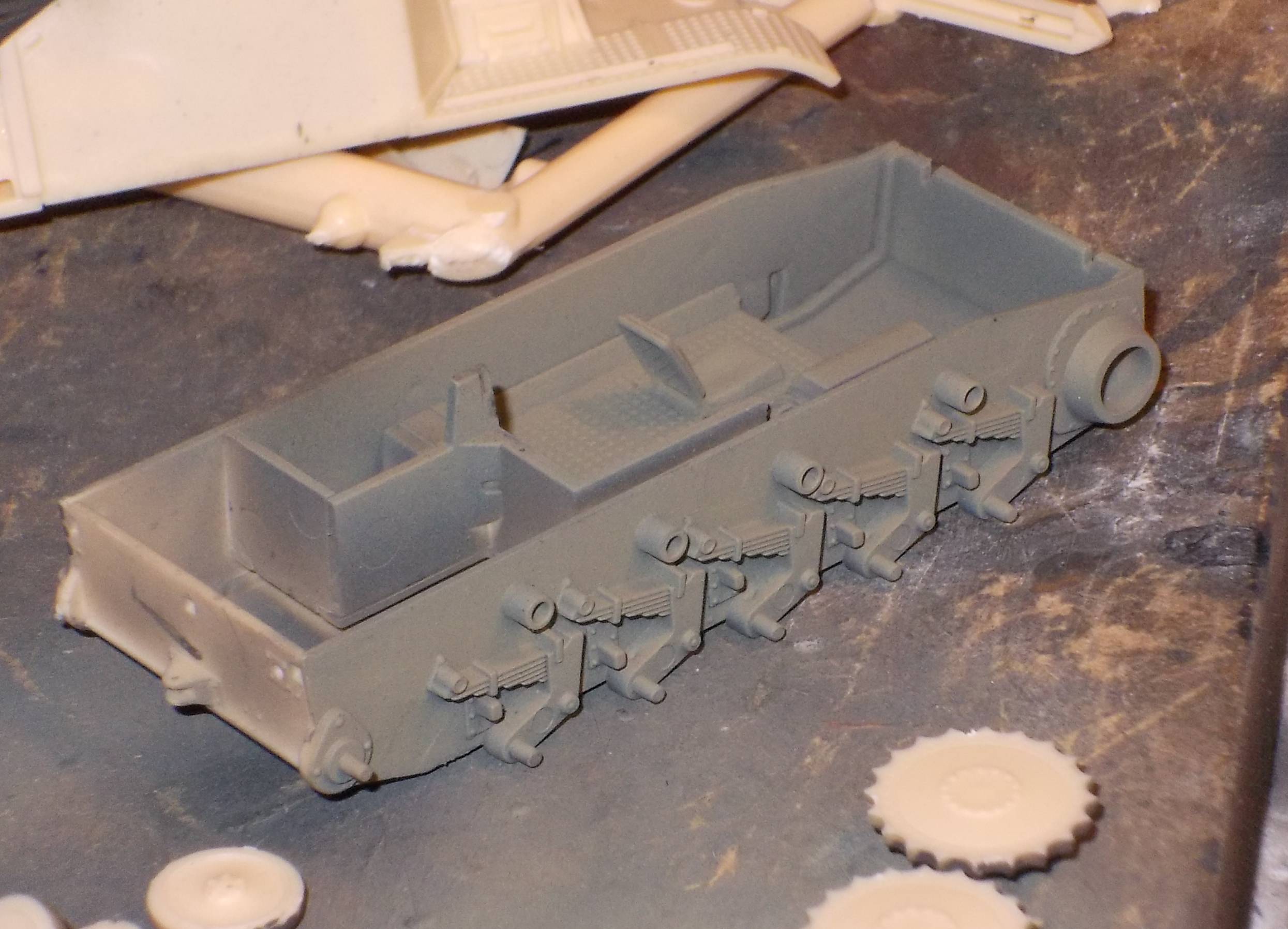
some parts to see how they fit. Then one thing led to another. The lower hull has a fair amount of
detail, which will be sufficient once the gun is in place. Still,
a quick glance at Achtung Panzer [2] taught me that I will probably
hang some more stuff to the inside of the walls.
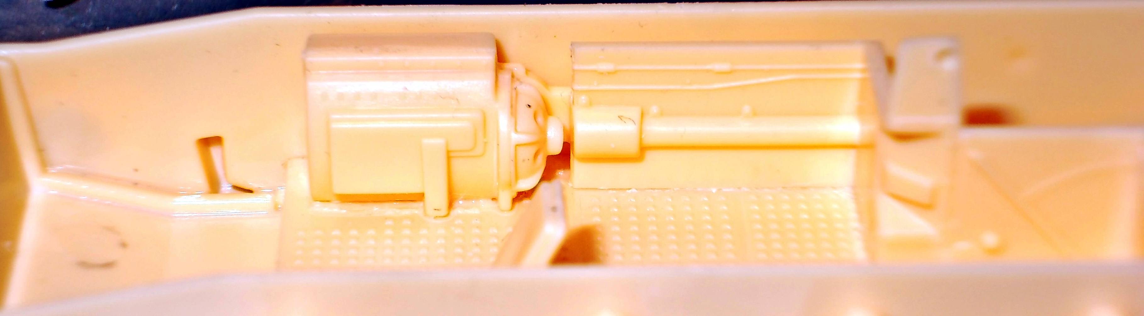
It might be due to the absence of locating
pegs, but the transmission (which is nice, by the way), doesn't connect
to the drive shaft. A small slice of stretched sprue will remedy this.
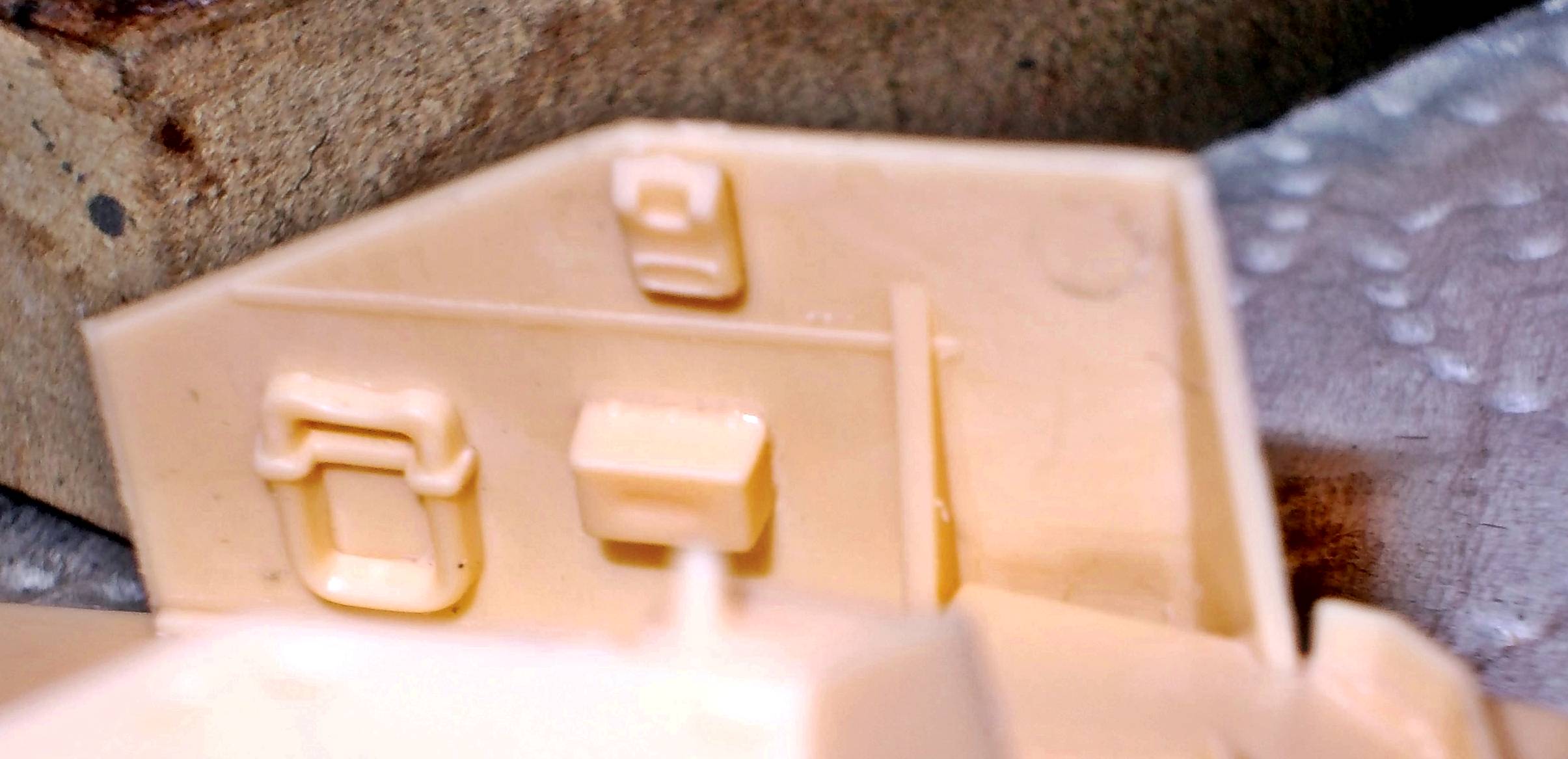
As you can see, there is a sink mark
on one of the boxes, and an ejector mark on the inside of the lateral
armor.
Another area that will require a little bit of work is this area of the fenders, where molding limitations resulted in a see through effect. A triangle of styrene sheet is already on its way to cover this.
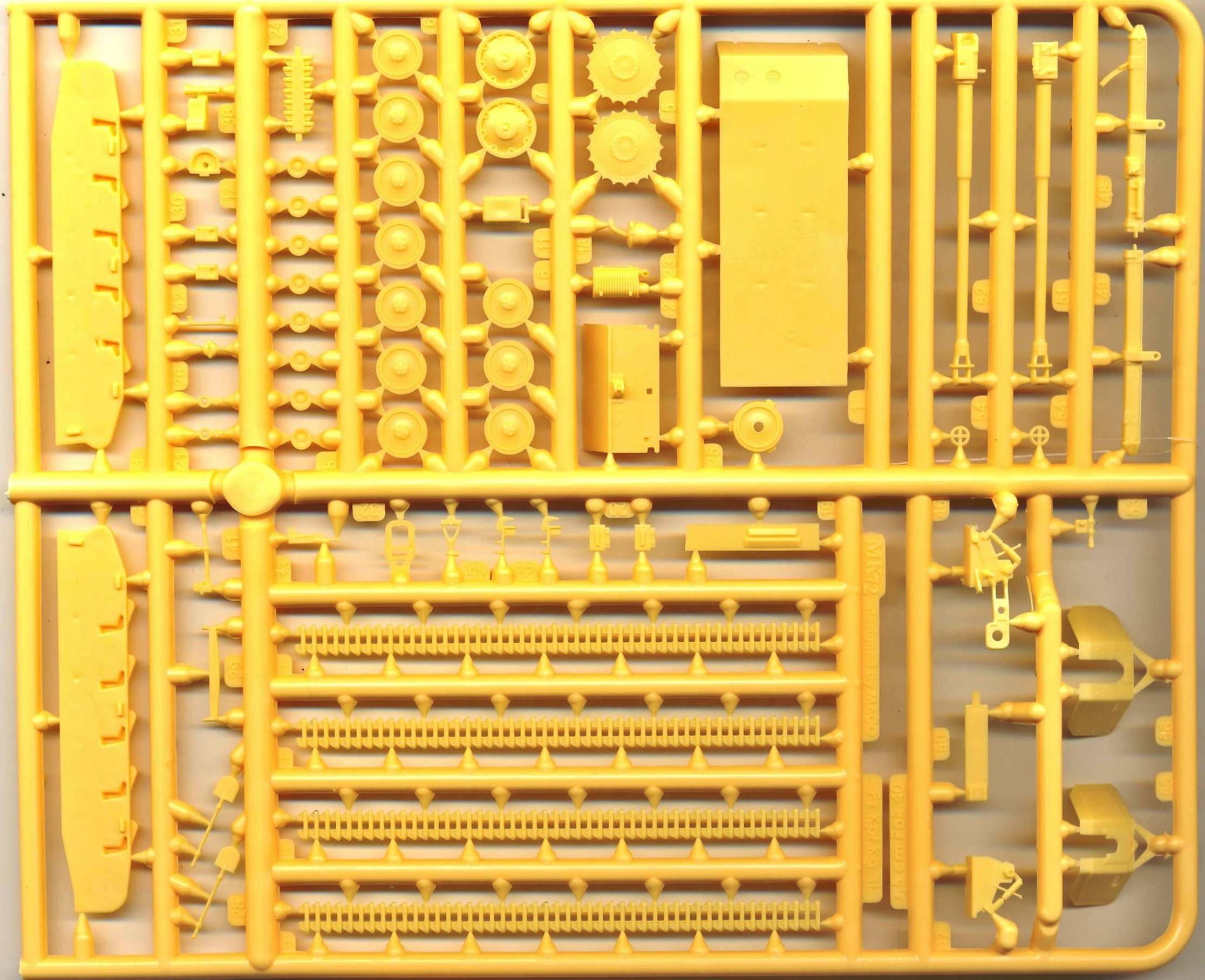
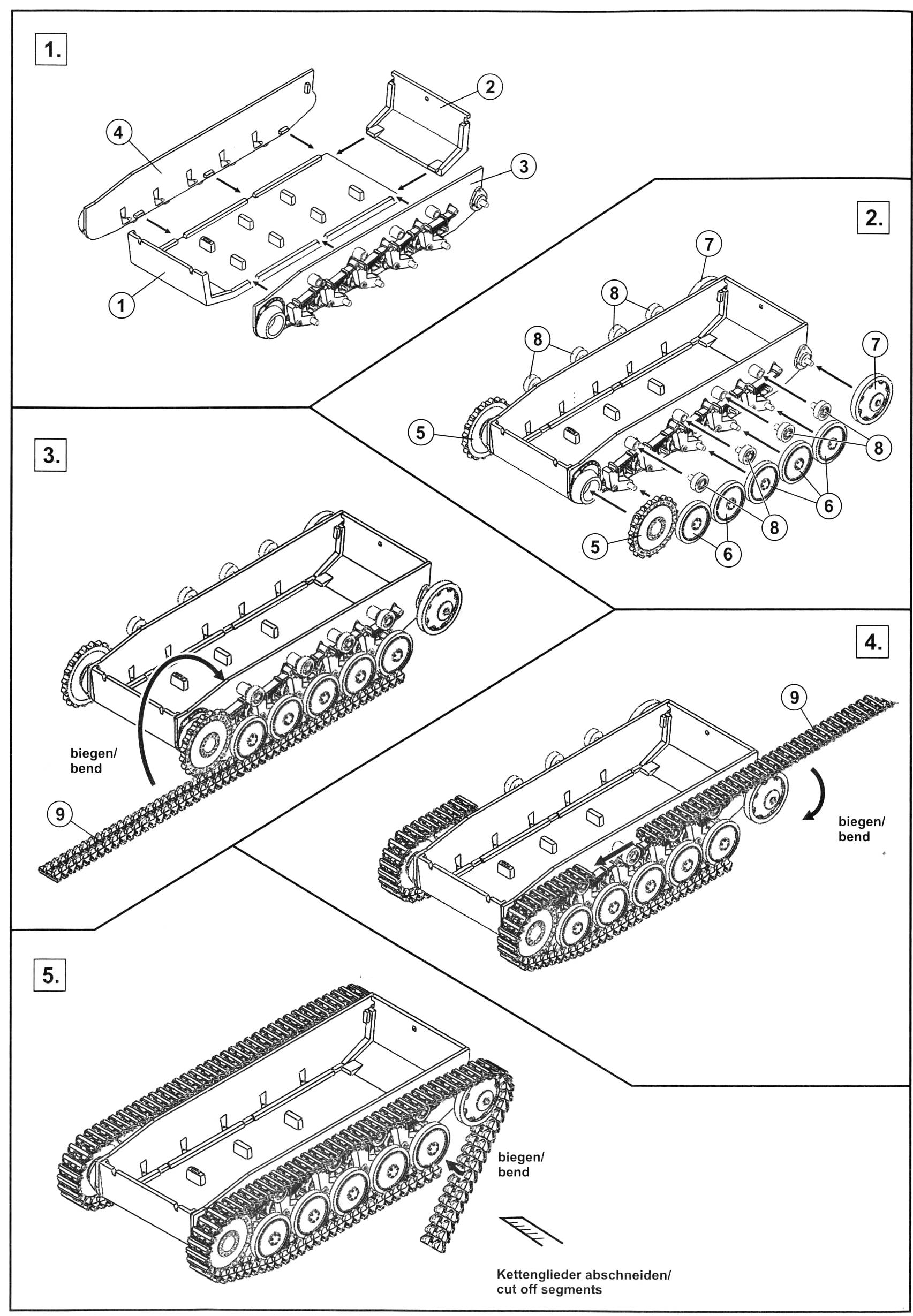
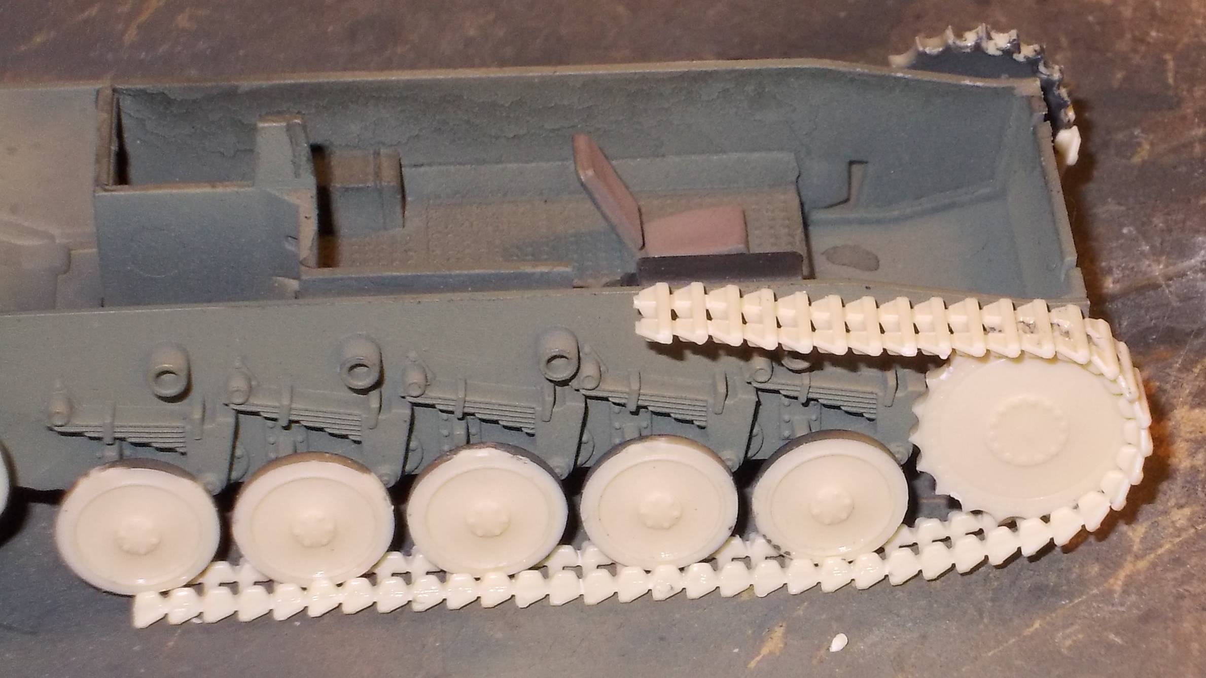
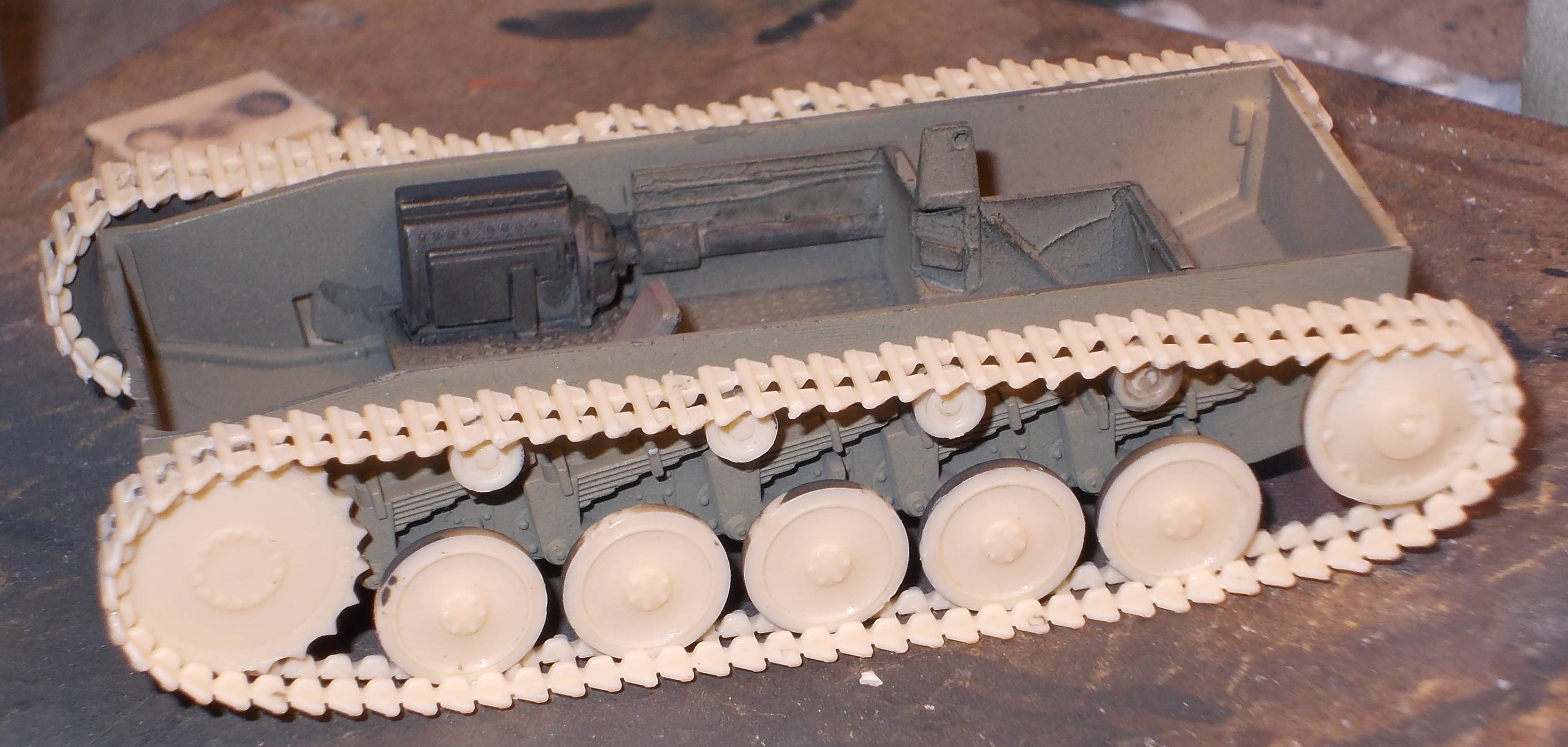
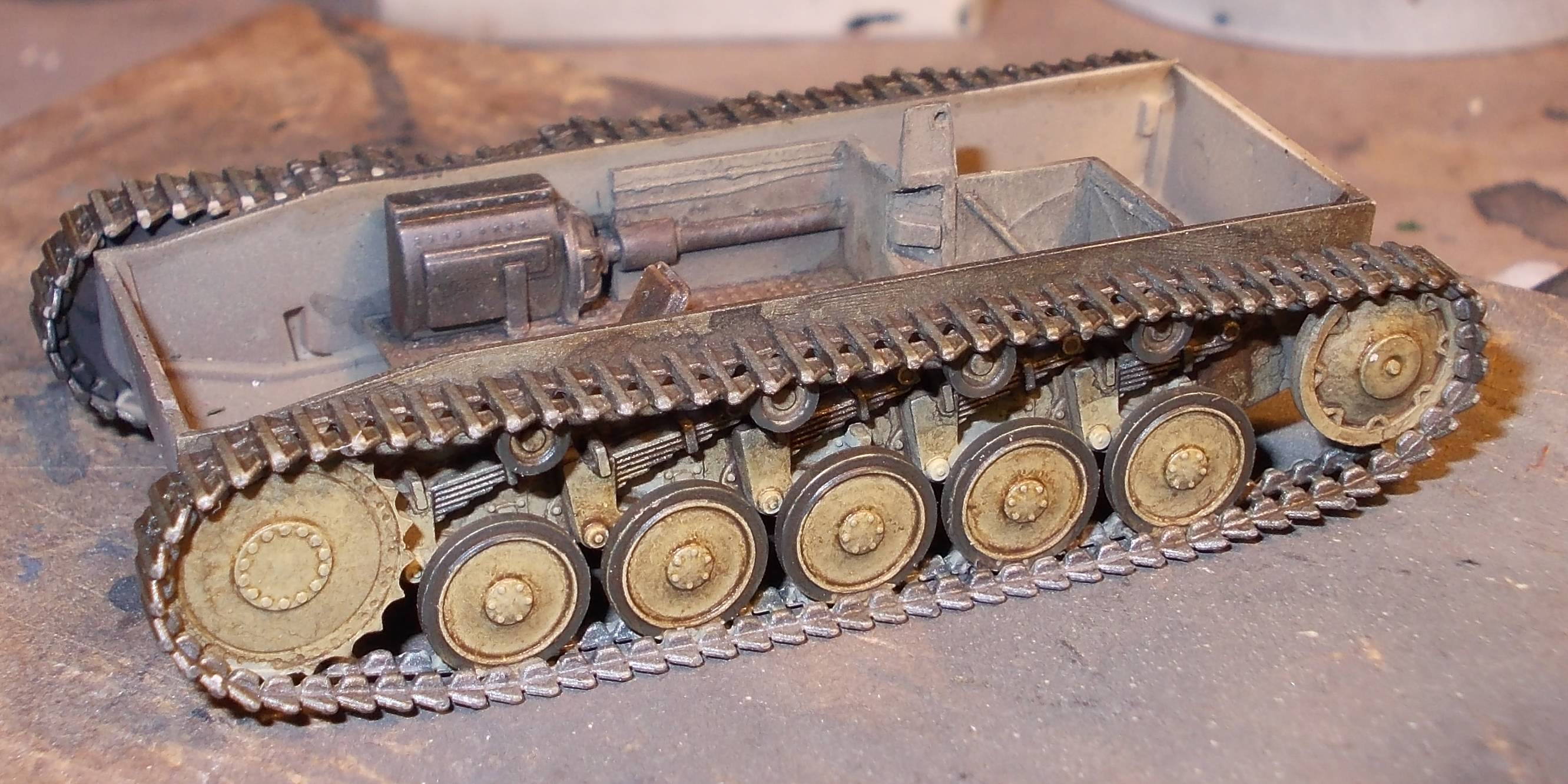
Phase III: Assembly and painting of the lower hull I will come back to the upper hull later, as I first need to finish the tracks and running gear before I can glue the lower to the upper hull. With the type of track that MK72 uses, it is well-nigh impossible to add the tracks after gluing both halves together, unless you cut them up which would undo the very reason of them being in long stretches. The use of two long stretches of styrene track is an innovative feature, pioneered on the Demag. They are very thin at the points where the individual track links join together, making them very easy to bend around the sprocket and idler. Being styrene, they can easily be glued to the drive sprocket, idler, etc. Of all the types of tracks that I've used over the last couple of decades (rubber band, link-and-length, Dragon Styrene) this is by far the system I prefer. I don't see any reason why it can't be done by other manufacturers of styrene kits. I would have preferred to have a single length, instead of two per side, but I guess this was not possible given the dimensional restrictions of the sprues. Apart from the speed of assembly, the main advantage is that you are almost sure to have perfectly aligned tracks, unless - like I - you manage to break one when bending it. They are very fragile, so take care. Another advantage is that sag can be easily reproduced.
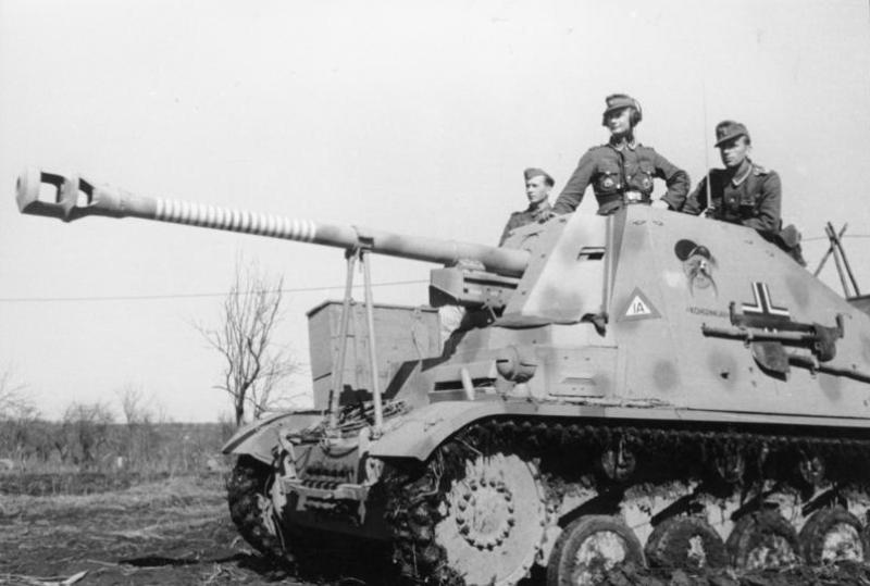
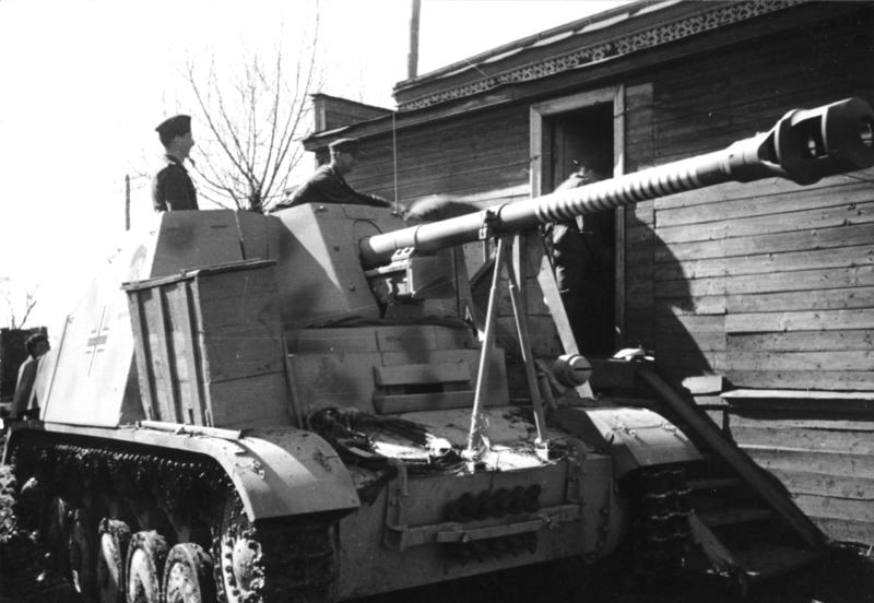
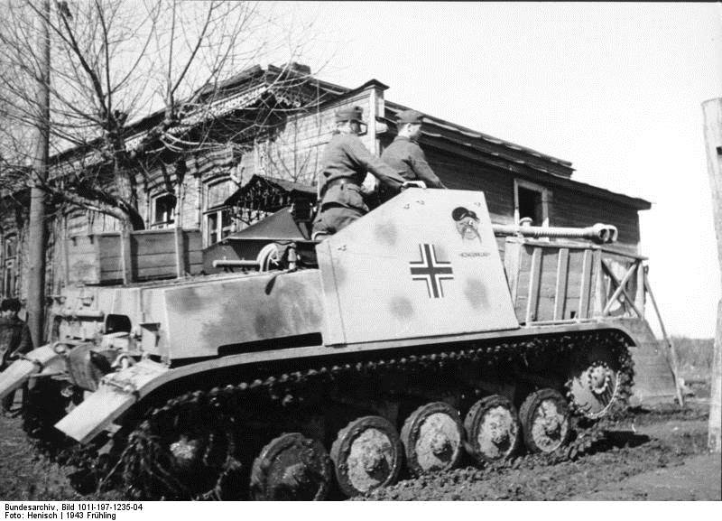
Realizing that a part of the lower hull would be very difficult to paint after installing the tracks, I decided to paint them beforehand. This meant I had to choose the paint scheme at this point. Not surprisingly, I went for "Kohlenklau", pictures of which were found on the MK72 website (copied above).
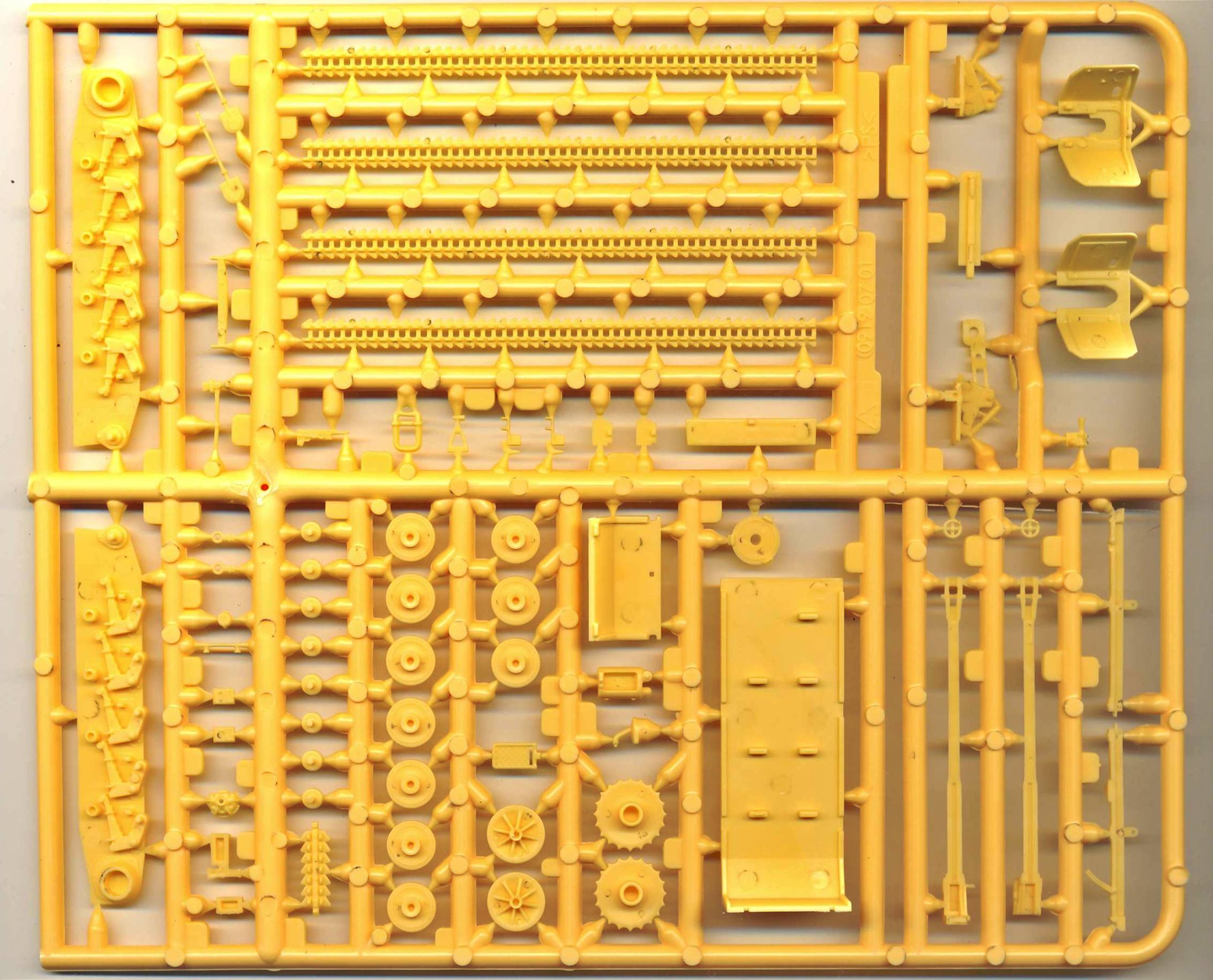
I chose to install the drive sprocket,
road wheels and idler first, then add the tracks, and then the top
rollers. This might seem weird, but building a UM Pz38t shortly before
this kit, got me scared as the different wheels, sprockets etc didn't
line up very well, making it impossible to get the tracks running
in a straight line. On top of that, spacing between the fenders and
the tracks was very limited. I guessed that doing the tracks first,
which were sure to be in a straight line, and which could be lowered
a bit afterwards, would avoid this problem if it presented itself
in this kit. There is plenty of track to go around. By plenty, I mean that you have to cut of a couple of centimeters, which you could turn into spare tracks. Might this be an indication that a longer hull variant (like a Wespe) is under way ? The tracks have nice detail on the
inside and on the outside, but due to technological limitations the
track pads are solid and not the skeleton type of the real thing.
I guess the only option currently available to do this would be photo-etched
tracks, if only for the needed structural strength. Meanwhile I also realized that the nice bit of machinery inside the hull is not the engine, but the transmission. It makes more sense now.
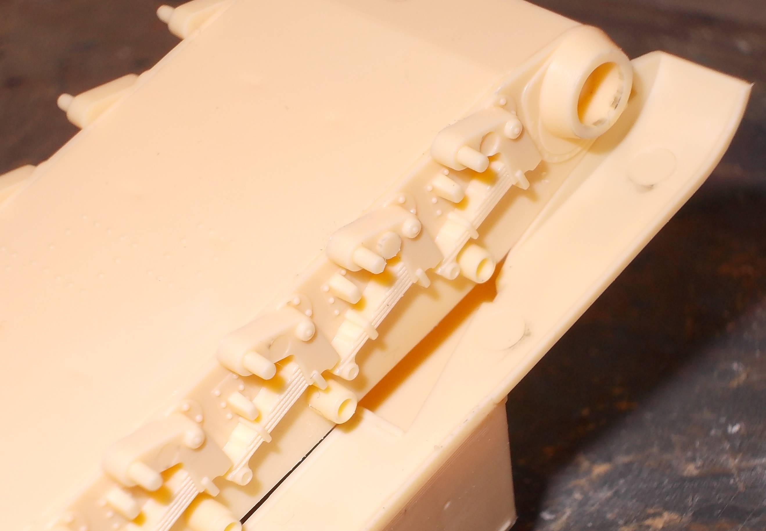
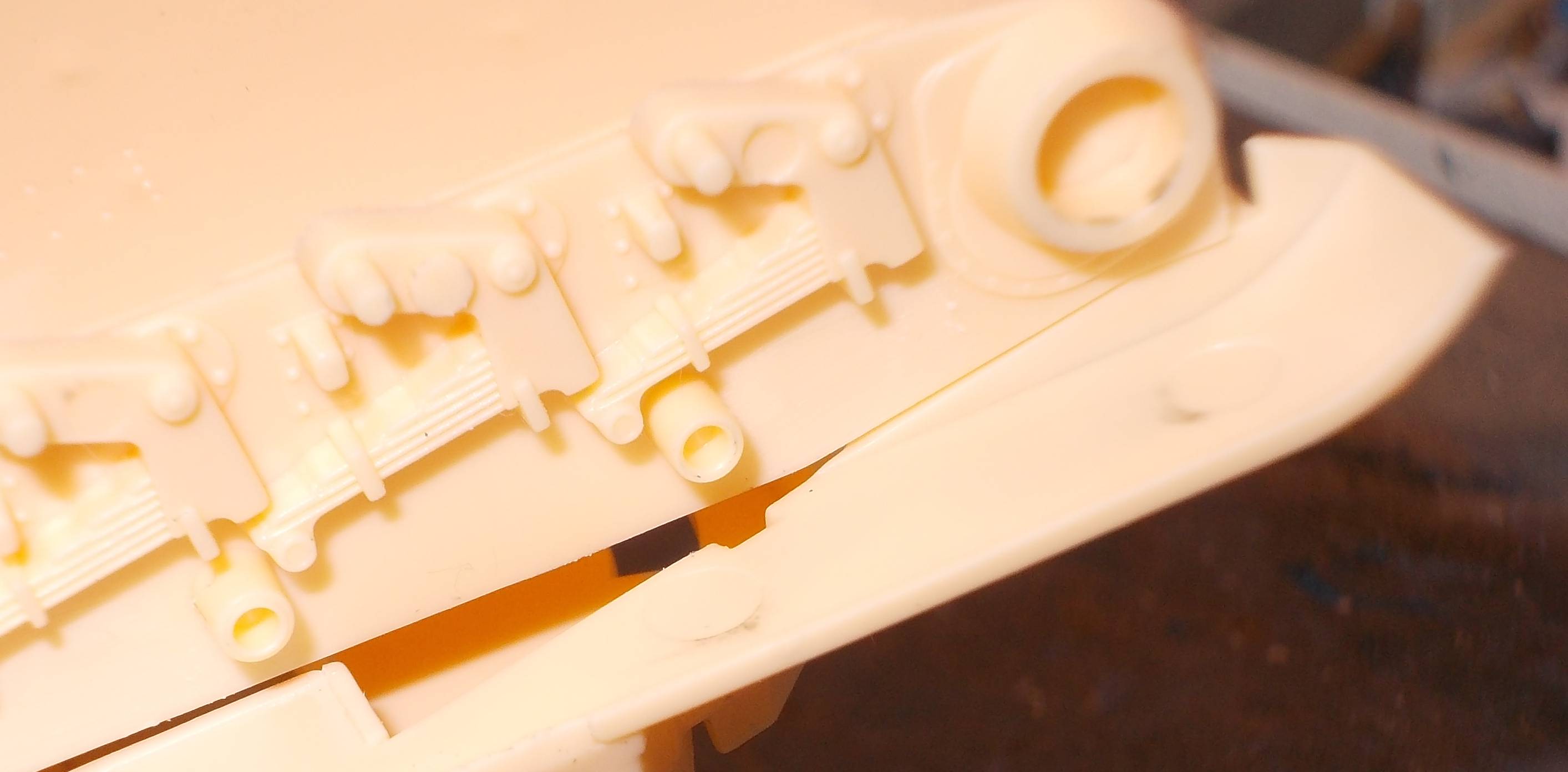
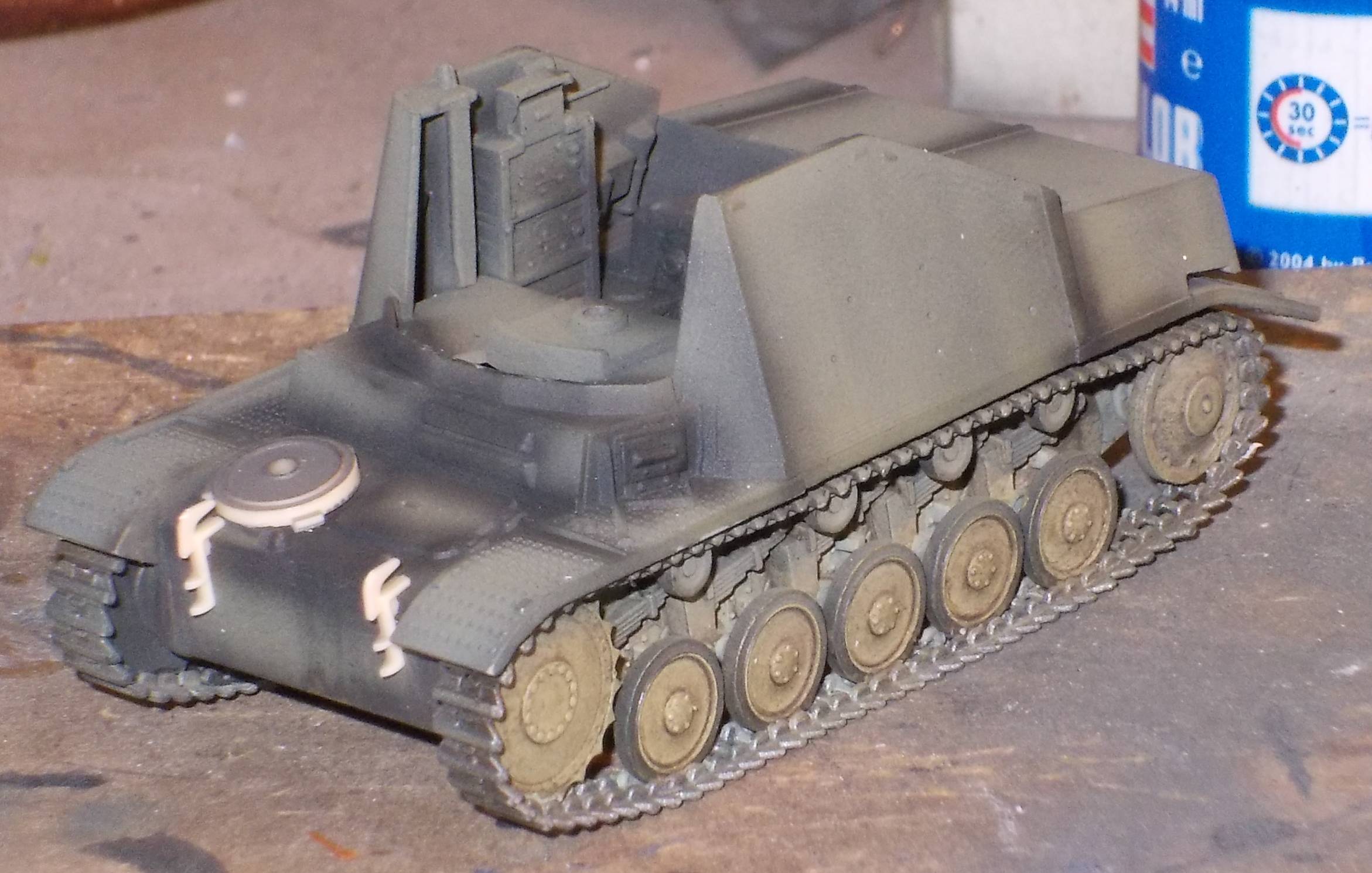
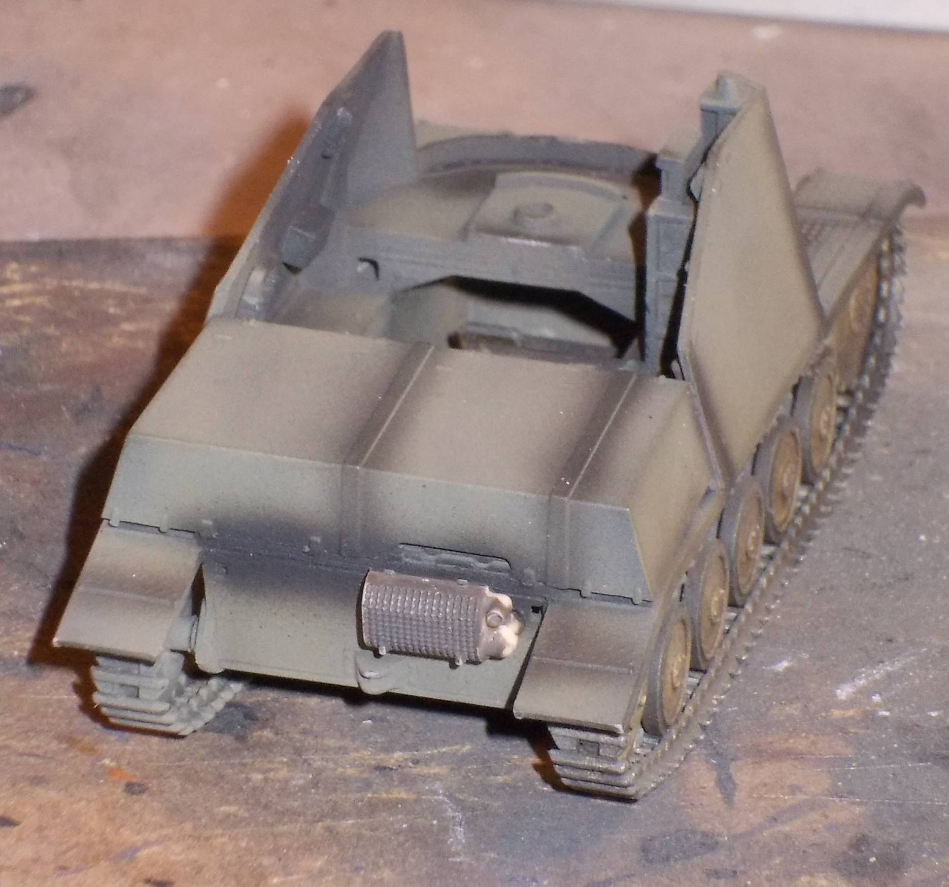
Phase IV: Mating the lower and the upper hull After finishing the lower hull and
mating as many parts as possible to the upper hull, gluing the two
halves together was relatively smooth sailing. I lavishly used superglue
to bond the two halves to be sure I wouldn't have an incomplete joint
which you could see through. The only difficulty I encountered was
in the area of the red arrows (pictures above). Cleaning up the joint
in this area after mating the hull was no easy task. I should have
perhaps waited with the upper armor plates until later. I also noticed
that it wasn't a good idea either to install the ammo boxes over the
engine compartment after installing these same armor plates as the
latter should slightly overlap the ammo bins. (It seems I really was
in a hurry when building this kit, which is rarely a good thing.)
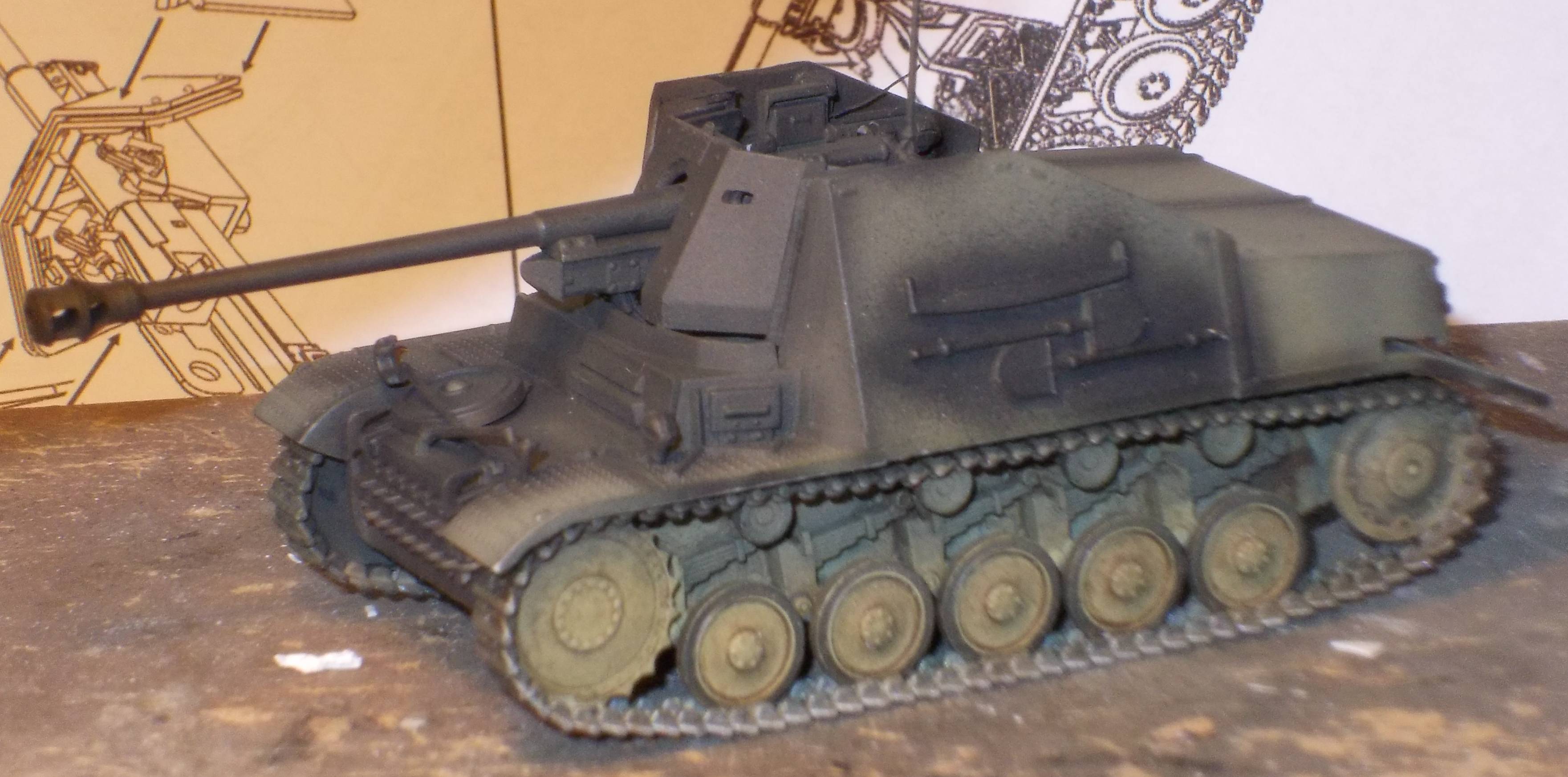
After assembly, I did some elementary pre-shading to make sure all areas that will be difficult to reach are painted. I then started adding some of the smaller bits. The exhaust has a hollowed out end, which is nice.
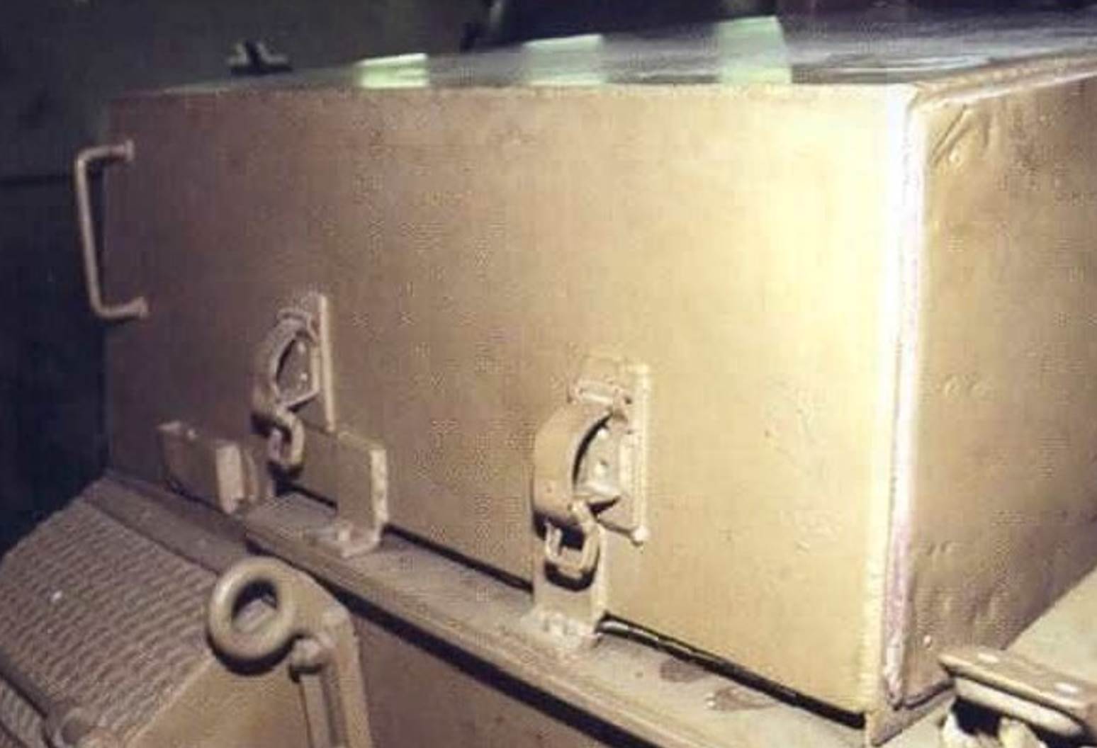
Phase V: Analyzing work to be done As I decided to build "Kohlenklau", I analyzed the pictures above and one of what seems a sister vehicle in [1]. I noticed that some details might be added and or altered: - The springs on the rear mud flaps.
(I don't think I'll bother with those). While looking at my references I noticed
that the kit has features of both early and late vehicles: Modelers in search of some scratchbuilding
can always add levers and other detail to the driver's compartment
and transmission (see [2]), but I don't think these will be seen with
the gun in place, and even less so when adding some crew figures.
(For those who would like to know, the Marder II had only three crew
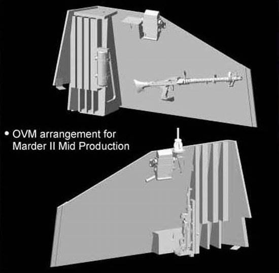
members.) What I will add however are a fire extinguisher from CMK (the position of which varied) and the MG34 (or at least the clamps for it).
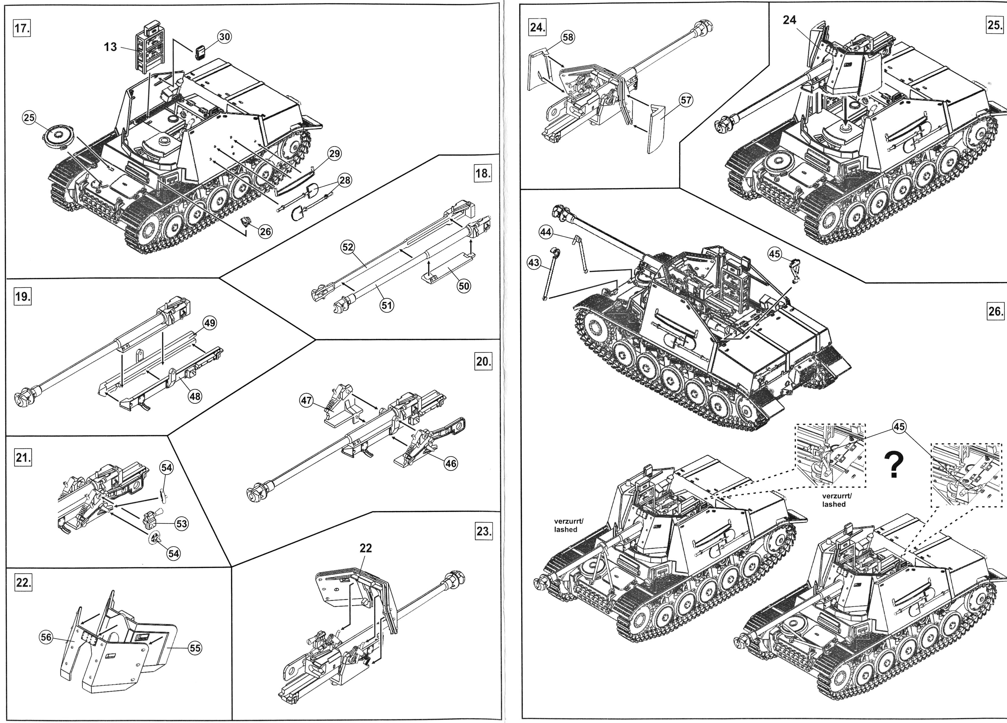
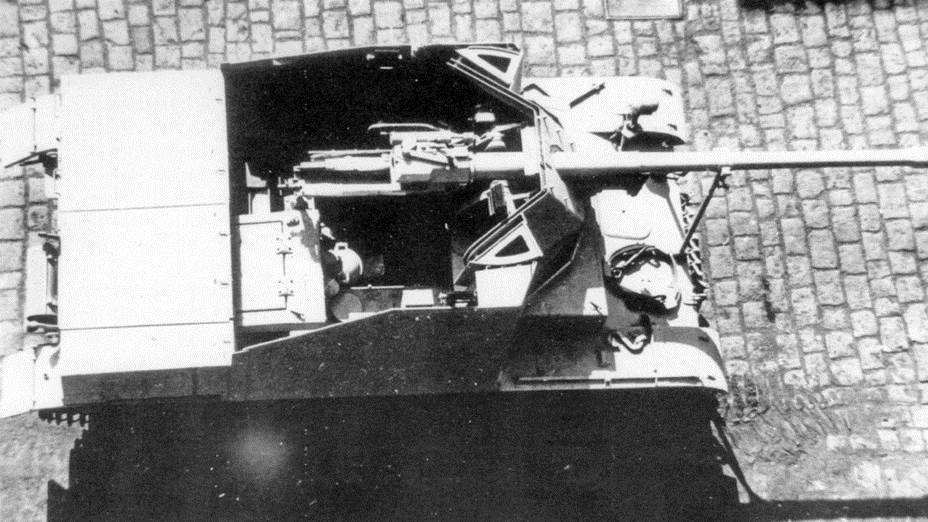
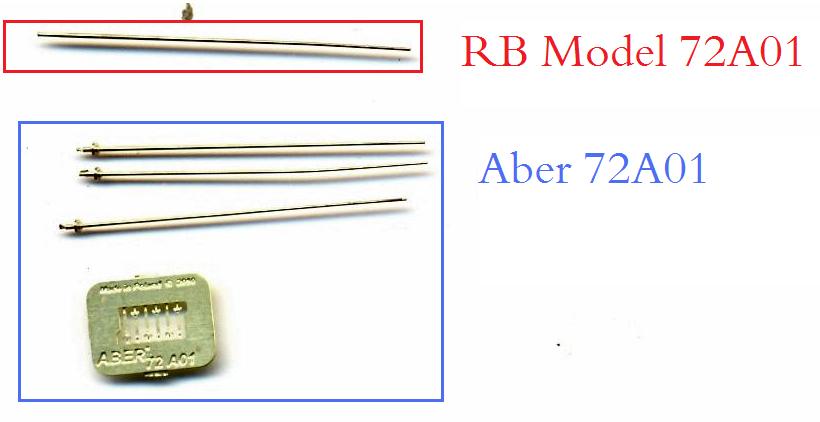
Phase VI: The final construction work, painting and decaling At this point, all that was left to install was the gun assembly. The way MK72 has engineered the gun, with the barrel split lengthwise, will allow for a well detailed muzzle brake without slide mold technology, but I tend to have a penchant for metal barrels, so I swapped it for the RB Model PaK40 barrel (72B05). This presumably comes with the flattened muzzle brake seen on the picture of Kohlenklau, but it looked quite round to me, so I flattened the flanges a bit more with a file (see discussion here). Note that the muzzle brake in the kit doesn't capture the look at all.
The kit correctly gives an outer and an inner shield, but the inner shield was marred with ejector marks on the visible side. Not difficult to correct, but engineering the sprues with the ejector marks on the other side would have saved me some pain. The installation of the gun assembly gave me the most trouble in the construction of this kit. First of all, you have to realize that the Marder II's interior is cramped, and the inward sloping armor of the fighting compartment doesn't help matters when you have to insert the gun afterwards, but that's not the whole story. When finishing the gun subassembly I noticed that I had to widen the opening in the inner shield. This might be due to the metal gun barrel that I used, but when I dryfitted the whole subassembly to the hull, I noticed that the gun pointed downward, even at maximum elevation. This was remedied by more sanding of the opening in the inner shield, but even with my best effort I could only get the gun (barely) level. At this stage, the opening is notably larger than the real thing. Dryfitting and checking with pictures showed that the whole gun sits a bit high on the vehicle. I wondered whether I had made a mistake during assembly, or whether the metal gun barrel is to blame, but I wasn't able to get to the root of this issue. So I took the whole assembly apart
again and sanded down the pivot for the gun. I then installed the
gun shield at the height I wanted it to be. In this way I was sure
there was no gap between the splash guard and the gun shield. I then
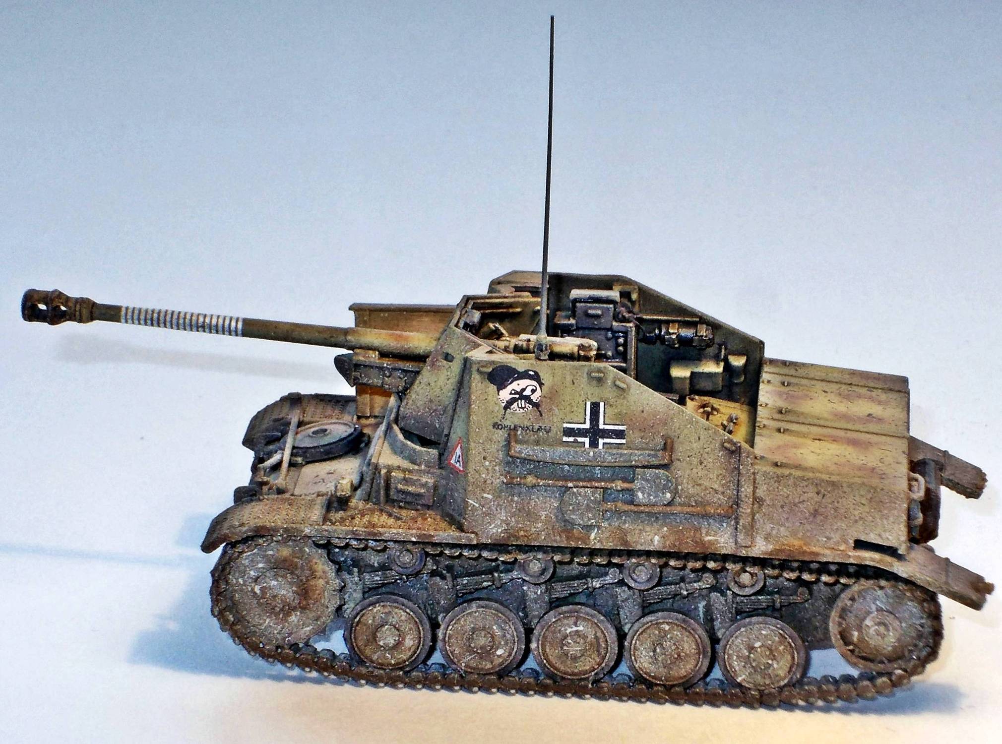
installed the gun cradle, and finally slid in the gun. I installed an antenna base from BP Resin and added it to the left armor plate, on top of which an antenna from RB Model was placed. Copper wire was then added to connect the radio set with the antenna base. (I am still wondering why the radio is on the right and the antenna on the left.) I still needed to add scratchbuilt headphones at this stage. Note that I have removed the MP40 from its bracket on the left of the fighting compartment, as I needed it lying around in the diorama I have in mind. I will use a Preiser part for that. The MP40 in the kit is not that very convincing in my view anyway. The same goes for the MG34 (which isn't included in the kit). The pictures of Kohlenklau (and sister vehicles) show two additional boxes added to the vehicle. I scratchbuilt the one on the right fender and left the one at the rear off. Painting started with a flat black base on top of which Tamiya XF-60 was sprayed. Blotches were sprayed free hand with Vallejo red brown.
The decals went on smoothly, but notice that the Kohlenklau cartoon is a bit too large, as is the handsaw on the left armor plate (see pictures above of the real thing). This results in some interference. The triangle marking on the rear of the engine compartment likewise was hindered by the axe.
Conclusion A beautiful little kit that goes together well, and needs very few additions/corrections. I have been told some of the sprues in this kit will be used for another kit in the near future.
Diorama setting The Marder was set in a diorama with the following constituents:
References [1] Panzer Tracts 7-2, PanzerJäger, T.L. Jentz and H.L. Doyle [2] Achtung Panzer 7, PzKpfwI/PzKpfw II, M. Bitoh, Dai Nippon Kaiga
Thanks to Matthias Conrad (Maco) for the review sample. |
| Back to MK72(MPK) Kit List | Back to Construction Reviews |
Article Last Updated: |
Back to Home Page |


.JPG)
.JPG)
.JPG)
.JPG)
.JPG)
.JPG)
.JPG)
.JPG)
.JPG)
.JPG)
.JPG)
.JPG)
.JPG)
.JPG)
.JPG)
.JPG)
.JPG)
.JPG)
.JPG)