|
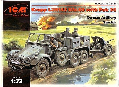
Overview:
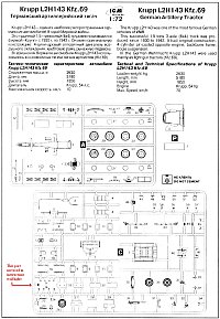 |
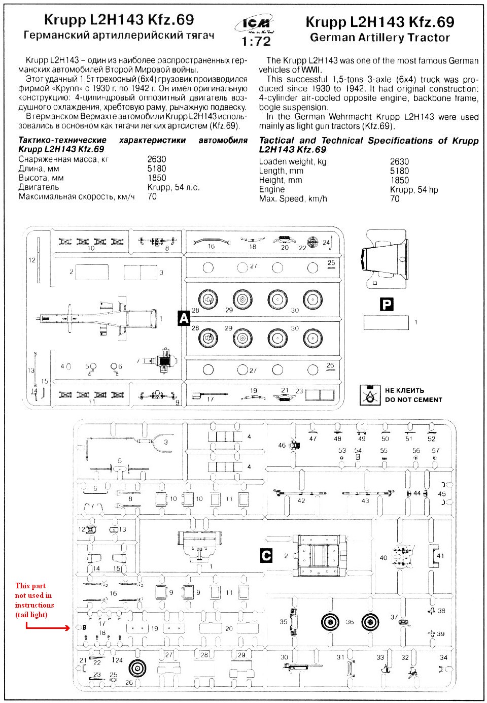
The kit consists of 130 parts molded in light grey plastic that is quite soft.
The parts for the truck totals 99 while the gun makes up the remainder. There is also a thin piece of clear acetate plastic for the
windshield glass upon which an outline is printed directly onto the plastic to ease cutting it to the proper size. There is also a
small set of decals and two instruction sheets outlining the construction sequence in five steps on one sheet for the truck and six
steps on the other sheet for the gun, using the familiar exploded diagram format. |
 |
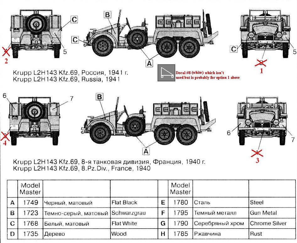
Decal sheet covers markings for two separate vehicles, both in overall Panzer Grey.
- Plate no. 195666, Russia 1941.
- Plate no. 40583, 8.Pz.Div., France, 1940.
Note: If you follow the instructions regarding decal placement you will wind up with mismatched plate numbers. For option one, the
instructions specify decals 2, 4, 5, but what should be used are decals 1, 2 & 5. And for option 2, the instructions say to use decals 1, 3, 6 & 7, but
what you really need to use are decals 3, 4, 6 & 7 (see corrections in the diagram to the left). Decal number 8 not specified anywhere and I assume it should belong to option 1.
|
Most of the parts had small seam lines which required a quick scrape with a sharp knife. On a few pieces
there was a small amount of flash, though it was easily removed for the most part. Ejector pin marks were sometimes not in the best of
places nor easy to remove. Many of the parts are very thin and petite just disintegrating when I tried removing them from the trees
or handle them. For example, the handles of the pick axes (part C5) were so thin that one of them snapped in two just from being pushed
across my worktable with a finger, and the four rifles (part C16) supplied with the kit weren't added as none of them survived removal from
the tree. They actually didn't stand a chance since they had either two or three large attachment points that had to be cut through to get
them off the tree and the cutting flexed the parts too much for them to stay together. For those tiny parts that did survive removal from
the tree, I found it easier to work with them by gluing them in place, letting them set thoroughly and then gently perform any scraping and
sanding needed while they were attached to the model. I found that a brand new blade in my knife worked best for this because its sharpness allowed
me to remove plastic with very little pressure thereby reducing the chance of breakage.
Personally I found the diagrams hard to follow and often vague, especially regarding the arrows used to direct the joining of parts.
For the most part I followed the steps as outlined in the instructions but found that I had to occasionally
stray due to the fear of breaking parts as I handled the model. To that end many of the small details that I felt should be painted at the
same time as the main body were attached when convenient near the end of the construction sequence. These included: grab bar (part C6), spare tire rack for
the gun (parts C21, C22, C23 and C25), headlights and tow hooks.
For this review I'll follow the instruction steps as outlined by ICM, pointing out spots where I deviated
from the instructions or found items of concern, plus add a few of my own steps.
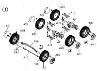 |
ICM Instructions Step 1 (Assembling the Suspension Units):
I built this as per instructions. Take care adding the suspension arms (parts A10 & A11) as
the transfer cases and axles are one piece units and the axles are very thin and fragile. I did not add any of the wheels which were left
off until the very last. |
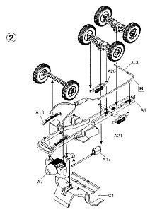 |
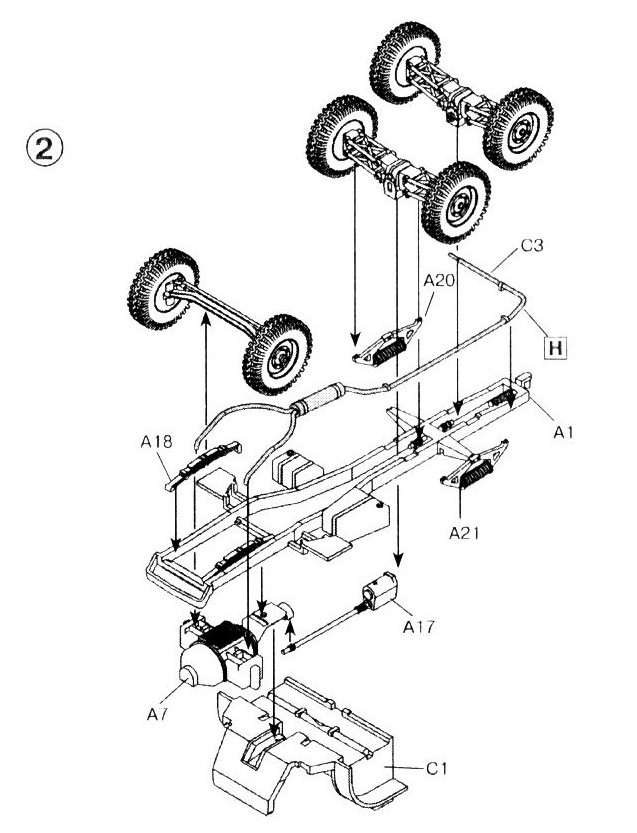
ICM Instructions Step 2 (Building the Frame and adding the Suspension Units)
Here again I followed the instructions as much as possible. I left off the front axle which was quite thin
and fragile until I had most of the frame and body work completed to avoid the possibility of snapping it while adding the other parts. The
exhaust pipe broke in two while removing it from the tree. I found the instructions a bit vague as to how to route it along the frame and also
avoid interference with the suspension parts, so I delayed any attempt at fixing it at this point and left it off until painting was complete.
There are locating notches in the frame for the rear suspension assemblies built in Step 1 but they are indistinct
and too short to accept the suspension units from Step 1. They had to be lengthened to allow the suspension units to fit onto the frame and also allow the
drive shafts (which are molded integral to the frame) to meet the differentials, which meant I primarily widened the notches toward the drive shafts.
Positioning the front leaf springs was a stumper until I realized that there were tiny, next to invisible notches, in the frame cross member
for them to fit into. The instructions were a bit vague regarding this.
The top of the gas tanks (molded on the frame, part A1) have hollow tops so I put a thin piece of plastic sheet over the
top to blank them off. At this point of the construction sequence I had no idea whether or not the other body parts would entirely hide the openings and
I didn't want to try adding a top to these after the body and frame were joined.
A test fit of the hood revealed that you could see through the engine compartment. I blocked the view by gluing a
section of tube, cut down the middle lengthwise, to the top of the engine (part A7). |
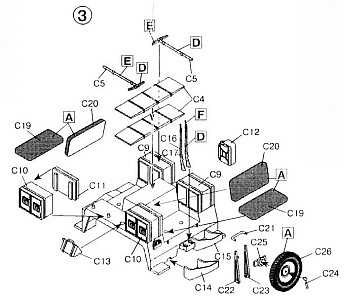 |
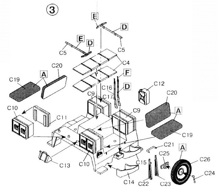
ICM Instructions Step 3 (Assembling Rear Passenger Compartment):
The foot rests at the rear of the body (parts C14 & C15) have very large ejector pin marks on the inside of the hollow
portion that proved next to impossible to remove due to their tight confines.
The rear panel of the driver compartment (the surface of part C1 that faces the rear seats of the passenger compartment)
requires sanding to remove ejector pin marks.
I had to trim a portion from the bottom of the rear compartment (part C2) where it meets the frame near the trailer hitch so it would
sit flush to the frame.
The inside of the rear fenders required some work. They have ejector pin marks that were problematic to remove due to
the tight space in which to work. Plus there are holes used to locate the lockers (parts C9, C10 & C11) on the top of the fender but they go all
the way through the fender and the locating stubs on the lockers are longer than the holes, which make them extend into the wheel well. So you will need
to trim off the stubs, then fill and sand them flush.
On my kit the right rear fender was not completely molded which required some filling and sanding to make it match the other side.
The kit supplied jerry can will not fit into the designated spot on the right fender under the bridging panels (parts C4 & C5).
I replaced it with a pair of cans from the spares box. |
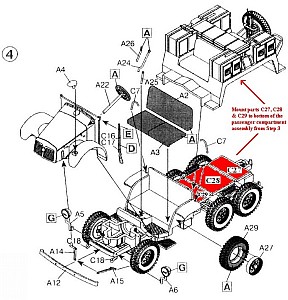 |
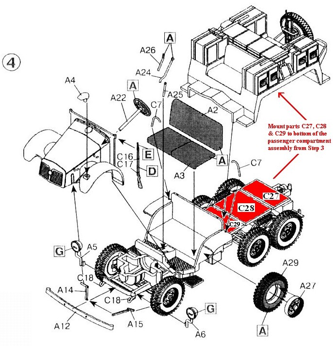
ICM Instructions Step 4 (Joining the Rear Passenger Compartment, Bumper and Engine Hood to the Frame):
Step 4 is where you run into a puzzler that took me a while to figure out. Three unidentified parts magically appear on top of the frame,
but there is no reference to them prior to this point in the construction sequence. Referring back to the parts diagram I eventually identified them (parts C27, C28 and C29) as the bottom panels for the rear
passenger compartment. Part C27 goes to the front, C28 to the middle and C29 to the rear (I've indicated their proper positions and part numbers in the
construction diagram with red fill). Mounting them to the frame before adding the rear compartment, as called for in the instructions, seemed like a recipe for disaster
since there is nary a location point for them on the frame. After some though I found it much easier to add the panels directly to the bottom of the compartment
piece (part C2). Also there is a large sink hole that needs filling in parts C27 and C29.
I found the instructions totally useless in identifying exactly where parts A14 and A15 went. I made a guess and attached them between
the front frame and the front axle to give extra support in this area. |
 |
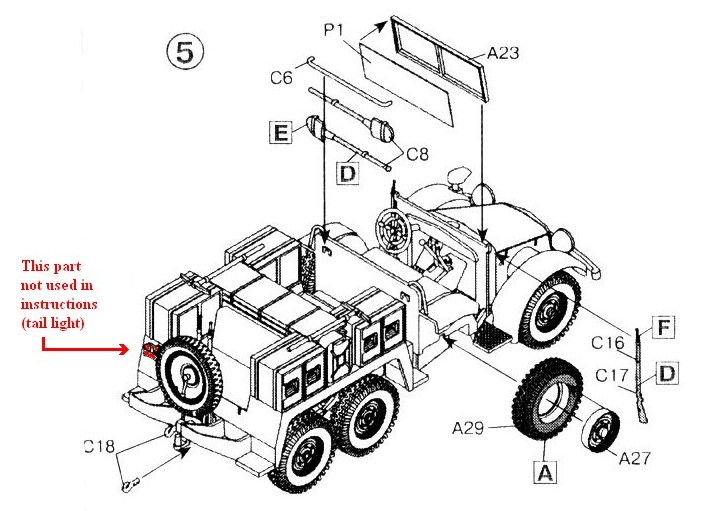
ICM Instructions Step 5 (Adding Remainder of Minor Details):
The windshield was another area of concern. There are two blobs of plastic attached to the outer edge of the frame which I suppose are
meant to be lights. In any case I found few pictures of Protzes with lights mounted to the windshield, so I removed them.
| Another problem with windshield concerns the missing ventilation panel that runs just under the main section of glass on the front driver's side of the
windshield (refer to diagram). Starting to feel a bit lazy
at this point I chose the easy route and dodged the extra work, and fear of breaking this delicate part, by adding a cover fashioned from Tamiya two part
epoxy putty. |  |
There are three different wheel rims supplied, all numbered identically (part A27): four shallow dished wheels with short hubs, two
with long rounded hubs, and two with long flat topped hubs. Being unsure as to exactly which went where I had to refer to my reference material for some guidance. The
four shallow dished wheels with short hubs go on the rear axles, the two rims with long rounded hubs go on the front axle, and the two rims with the long flat topped
hubs are for the spares mounted to the body.
The wheel rims were most annoying to work with. The edges are very thin and fragile so you need to be careful removing them from the
tree and fixing the attachment nubs or you'll notch edges of the rims.
The neck on the Notek light was too long and it was trimmed some for length.
The rear tail light (which has no part number) appears on the rear of the vehicle in this step but once again there is no reference
to it earlier in the instructions. From what I could figure out from my references it is of a later design and as my plan was to use the 1940 French
campaign markings I replaced the kit part with a section of plastic rod to represent an earlier round style brake lamp. |
My Step 1 (Adding the Detail Parts from Previous Steps plus Extra Detailing):
The kit's two shovels were discarded. For some strange reason they were molded with the mounting strap across the inside
face of the blade making them look rather odd. I replaced one of them from the spares box and mounted it to the top of the bins on the left fender while the
other went into the spares box. I only used one pick axe as it was the one to not break and I didn't feel like trying to repair the other one. I found
one picture with a Protze sporting a fire extinguisher. I liked the idea of adding one of these to the kit and procured a copy from the spares box. I also
added a tarp made from Tamiya 2-part epoxy to the rear facing seat in the passenger compartment.
I lost the retainer for the gun's spare wheel (part C24) which forced me to construct a replacement using some plastic rod and
sheet and then I glued it directly to the hub.
I scratch built signal indicators, which are a very prominent feature of this vehicle. There are no plate holders so I added
some cut from plastic sheet. I'm puzzled as to why these important features were omitted when most of the other minor details were included.
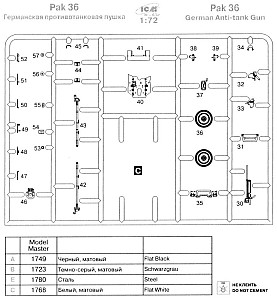 |
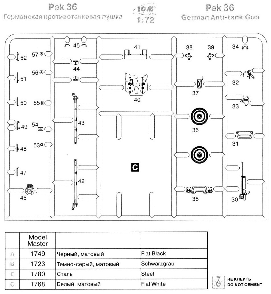
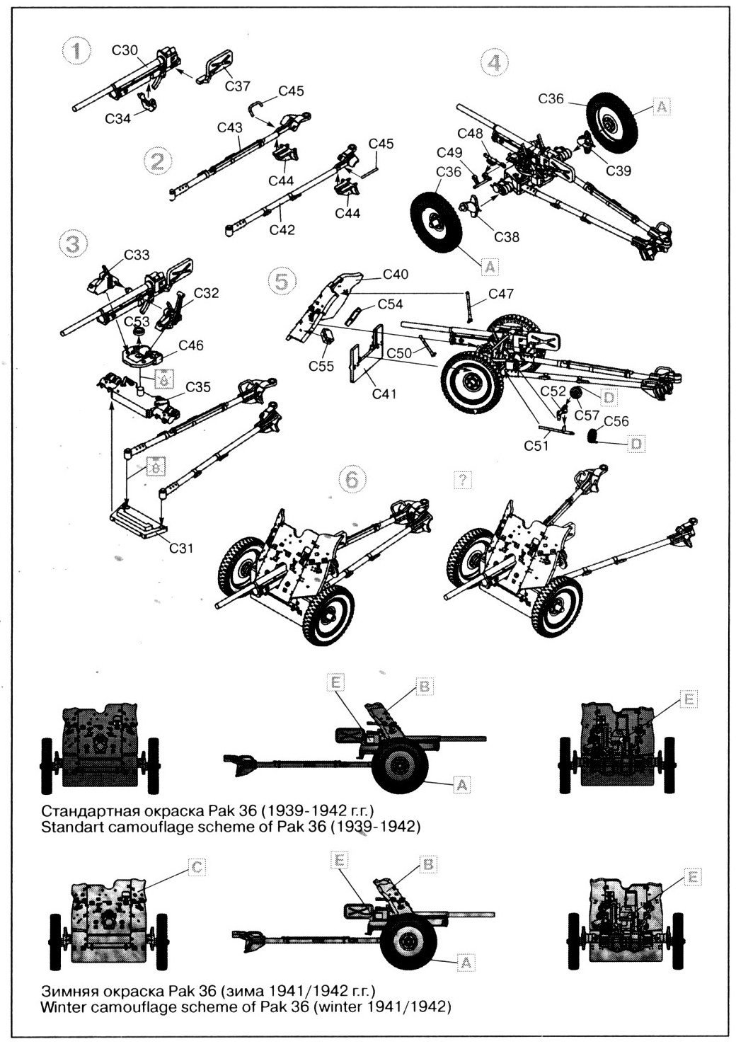
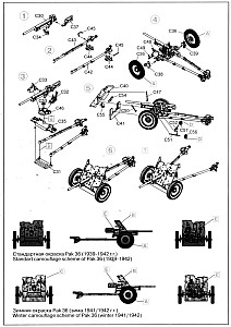
| ICM Instructions (Building the Pak 36 Gun):
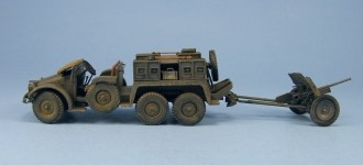
You get the option of building this as towed gun or one in firing position. I chose the towed configuration. Here again the
vague instructions left me scratching my head in bewilderment at the placing of parts. I had to guess as to exactly where parts C54 and C55 mounted to on the
inside of the shield. The same applied to the elevation and traverse wheels, which also proved to be a pain to put together due to the miniscule parts and its multi-part
construction.
The only modification I made to the gun was to alter the barrel's travel position. Adding the parts as they come from the box will
set the barrel level to the ground and I wasn't sure if this was going to allow enough ground clearance when mounted to the vehicle's hitch, so I cut off most of the
elevation gear (molded to the barrel, part C30) so the barrel point upwards somewhat.
The hitch loops on the end of the Pak 36 legs (parts C42 & C43) need to be opened up if you want the gun to be towed.
The gun's left axle part (C38) was missing its stub for mounting the wheel so I drilled a small hole and added a stub from a
short section of plastic rod. |
 |
My Step 2 (Painting, Decals and the Remaining Parts):
Painting and was done with Modelmaster enamels and decals were applied after a coat of Modelmaster Glosscote was applied.
Weathering was done with Modelmaster and Aeromaster enamels (both dry brushed and spray painted). Just before the final coat of
Aeromaster acrylic flat I added all the parts that I had left off earlier to ease the painting process: seats, shovel, pick axe, wheels and rims (both for the gun
and truck), windshield, front suspension stabilizer bar (part A13, which also required some trimming for length to get it to fit between the wheels), exhaust pipe, steering wheel and stick shifts.
Working with the rims and tires revealed another fault. The thinness of the rims resulted in damage if too much pressure was applied while pushing
the rims into the holes for the tires. I wound up with a few bent edges (take a close look at my rims to see what I mean).
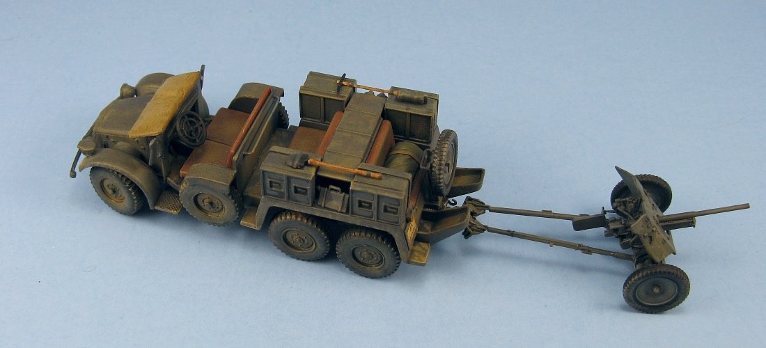
Conclusion:
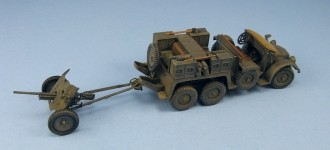
This was a build with many ups and downs with a lot to like about the kit and a lot not to like.
There is lots of detail crammed into both the truck and the gun. Construction will require some patience on the part of the modeller and a
few pitfalls along the way that will need to be dodged. In the end you get a nice looking kit of this important German softskin while the Pak 36
is a real little gem.
References:
- Krupp at War: The Legendary Krupp Protze & Other Vehicles, German Trucks & Cars in World War II Vol. V, by Reinhard Frank, Schiffer Military History, West Chester, PA, 1992 ISBN: 0-88740-399-9
- Various web sites


Review sample purchased by the author.
|