|
A Brief History
The Wasserfall was one of a number of German anti-aircraft missiles (SAM) designs explored during the war as an attempt to defend German strategics target from
growing Allied bombing raids.
Initial design and specifications for this missile was worked on through 1941-1942, with prototype launches starting in March of 1943. The airframe
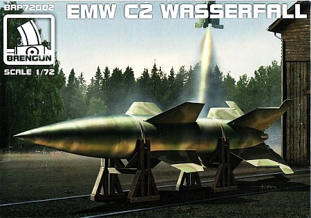
was much like a small V-2 rocket, with extra fins located approximately mid-fuselage. On the early prototypes (W1 series) these fins were quite large and were
offset 45o from the steering fins at the base. The fins were later reduced in size and mounted inline with the rear fins (W5 series).
A smaller version, reduced in size by approximately 1/3, and using more non-strategic materials was planned (W10 series).
The rocket motor used two fluids for fuel - Visol (vinyl isobutyl ether) and SV-Stoff
(RFNA 'Red Fuming Nitric Acid' - 94% nitric acid, 6% dinitrogen tetroxide), forced into the combustion chamber by pressurizing the fuel tanks with nitrogen gas released
from another tank.
These liquids are hypergolic, igniting upon contact to provide thrust. Steering the rocket was by manual command to line of sight (MCLOS), where the operator employed
a joystick to guide the rocket, tracking its flight via the exhaust plume. Radar was also being developed for night time and poor visibility operations.
A warhead of 100 kg was originally planned, but because of accuracy concerns it was replaced with one of 306 kg to provide a larger blast radius.
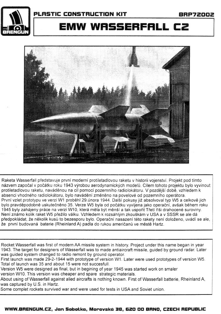
It appears that no Wasserfall missiles were ever launched operationally. The Brengun instructions claim that a battery named Rheinland A was captured
by American troops at Hartz, though I have found nothing anywhere else to support this claim. Captured examples of the Wasserfall were used by the United States after the
war in their Hermes project.
Contents
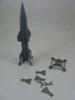
The kit comes with 39 parts, all on a single sprue, and molded in a medium grey semi-hard polystyrene plastic. The plastic pieces are fairly well molded
with next to no flash but having some seams due to mold misalignment. No decals are included.
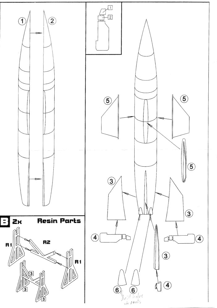
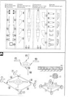
The instruction sheet consists of 6 separate steps outlining
the construction sequence. The second page has the parts layout. There are 8 parts are not used and they are greyed out. Four of the parts are for a set of smaller fins
for which I'm not sure why they are there. I would have assumed that including the larger fins of the earlier prototypes would have made more sense. The other four unused
plastic pieces are for a single stand and the crossmember of a second. Why they are there is another puzzler, though I suspect that someone goofed during the design of
the sprue layout and omitted the set of uprights for the second stand,
and when the error was noticed Brengun had to supply another set of stands an additional 6 resin pieces. Whatever the reason, the resin parts are well cast. There is also an etched
metal fret containing three parts for two straps and an octagonal mount that goes on the trolley.
Construction
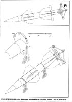
The instructions would have you start with building the trolley. This may be appropriate if the missile is to be mounted horizontally on its stands, but for a vertical mount
that I wished to do, I felt the trolley would be best left to the last. This way any alignment issues that may cause the missile to not stand vertical could be addressed before the
glue set. So I moved on to the body.
The body is completely hollow. I added a plastic tube inside the rear to remove the large void look and to allow me to push a stick up the rear to use as a handle
during painting. With careful aligning during gluing the seam along the body is easily dealt with and next to no filler will be needed.
Both sets of fins (parts 3 & 5) need some sanding and scraping to remove the slight mold misalignment seams and to adjust their bases to better fit the curve
of the fuselage. Brengun has conveniently added lines molded into the hull to help with placement of the fins. Make sure that before the glue sets to align the fins with
each other.
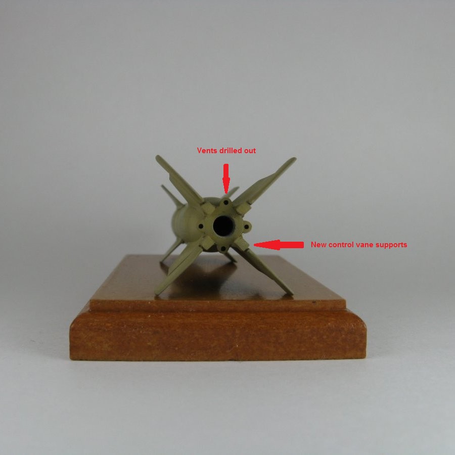
Holes were drilled into the bases of the vents (part 6) and they were then glued to the body. Once again Brengun indicated where they should be placed with engraved
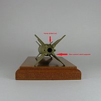
lines in the body. Next I cut the pieces marked (1 - exhaust control vanes) & (2 - control vane supports) from the control surfaces (part 4) in preparation for their replacement later. What little I could find
in my references showed the Brengun representation to be questionable. The control surfaces were put aside to be added later.
The step to assemble the stands was skipped and the parts tossed into the spares box.
The trolly was assembled at this point. The octagonal mount (part PE1) was folded at each of the joint lines and the ends were glued together. This was done
first to allow the cyano glue to thoroughly set before I tried adding it to the base. Next I drilled out the six holes in the wheel hubs. It must be noted here that I
could find no corroborating evidence for six holes. All photos that I could find showed a spoked wheel with only four holes.
Then I moved on to the base core (part 12) and its spokes (parts 10 & 11). Here's where
the first real difficulties emerged. The end of the spokes that abut the base are longer than the corresponding attachment points, meaning that the spokes should be
replaced or you will have to decide whether the extra length is acceptable and mount the spokes as is, which will result in a small jut above or below the base.
I chose to mount them as is and have the extra length jut below the base core where it would be hidden from sight. After this assembly had set long enough that it wouldn't fall apart during handling, I added the outer frame
rails (parts 8 & 9). Again we run into another size difference, where the end of the spoke is taller than the diameter of the frame rails, resulting in
another choice as to where the rails should mount.
I chose to have the rails sit at the bottom edge so I could put the whole assembly on a flat surface in an attempt to get everything level. I used slow setting
Testors liquid cement to allow time to adjust the parts before the glue totally set.
After this I added some missing detail. The spokes on the base that run
parallel with the wheels need to have a lip added, which I did with some thin styrene strip, and a set of loops found on the front and back frames were also added.
Lastly, the brass octagonal mount was glued to the base.
Moving back to the rocket, the control surfaces were glued to the rear fins and then the rocket was perched on the base to see how well
everything sat. Then I added four new control vane supports fashioned from some square styrene rod, glued them to the rocket's butt end and added small sections of round
rod between them and the control surfaces. To ensure that the rocket sat solidly on the base, I once again placed the rocket on the brass mount
and marked the spot on each of the four faces where the rocket rested. Then on the opposite side of the marks (i.e. on the inside of the mount), I glued a small section of
square rod so that it sat flush with the top edge of the mount. These small sections of plastic will provide a wider surface where the new control vane supports
will sit and a spot where I can put the cyano glue to attach the base and rocket together.
It would have been nice if Brengun had included a small section of rail as a display option. Since they didn't I built a small rail
section and display base for the trolley, all fashioned from pieces of styrene sheet and T-beam rod.
Painting & Markings
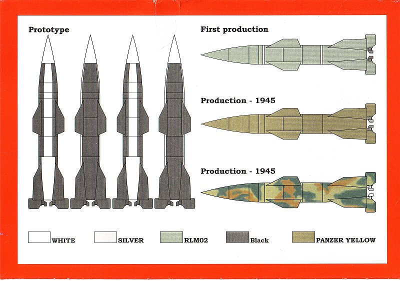
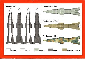
Four colour schemes are presented on the back of the box:
- Prototype (versuch) scheme in black and white.
- Pre-production scheme in what I assume is overall RLM02 grey with two silver (i.e. natural metal) bands where the stowage straps are located. This appears to be the
colour scheme of the rocket seen in the Youtube video [5].
- Production scheme in overall armour sand-yellow.
- Production scheme in overall armour sand-yellow with random patches of brown & green.
Options 3 and 4 are probably speculative, but this did not deter me from painting my rocket as option three, along with some artistic licence by adding the silver stowage strips.
Since it appears that the rockets were kept protected from the elements most of the time, I applied no weathering. I did weather and heavily chip the transport trolley
on the assumption that they would be reused between launches. The base got lots of staining as well.
Conclusion
Outside of the accuracy issues with the trolly this is a very nice kit indeed. I appears to scale out quite closely to the measurements found in my references. I
hope that Brengun will continue down the path so admirably started with the Wasserfall and give us more of the late war German surface-to-air missiles like the Enzian,
Rheintochter and Schmetterling.
References
[1] German Secret Weapons: Blueprint for Mars, Brian Ford, Ballantine Books, New York 1969
[2] German Secret Weapons, I.V. Hogg, Arco Publishing, New York 1970 SBN: 668-0-2337-6
[3] German Guided Missiles, Heinz J. Nowarra, Schiffer Publsihing, Atglen 1993 ISBN: 0-88740-475-8
[4] Wikipedia
[5] German Wartime Newsreel footage found on Youtube
[6] Luft46.com
[7] Norbert Brügge
Review sample purchased by the author.


 |
 |
 |
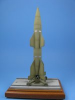 |
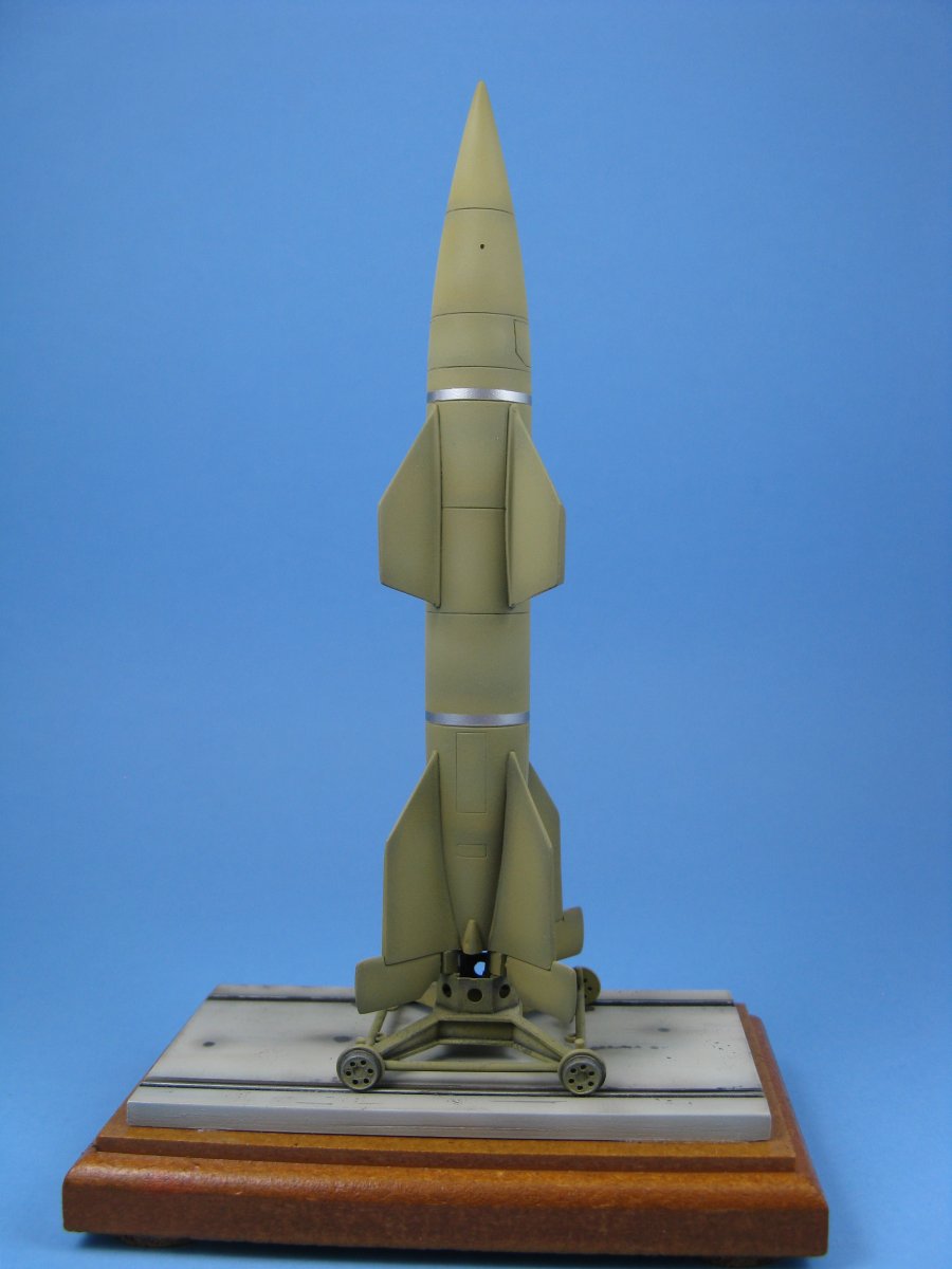
| Wasserfall nearing completion |
Modifications to the
base end of the rocket |
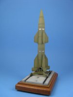
Completed kit |
| Reference Pictures |
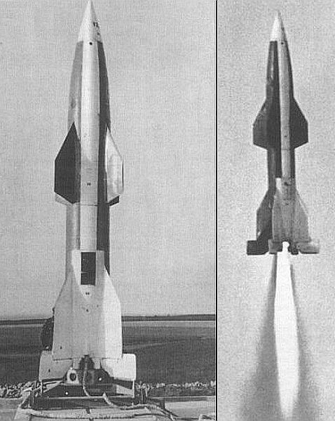
Two pictures of a prototype rocket. The V (for versuch) and what looks like the number 2 (though it could be a 7) are found near the tip of the nose cone. This appears to be
the inspiration for markings option 1. |
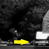
A still image from the German Newsreel video on Youtube. Though it's not the best of pictures, if you look at the front
wheel of the transport trolly (yellow arrow) you can see that it has a four spoke design of some sort with a single hole between the spokes.
This does not match the kit's wheel, which is flat faced and has 6 circular openings. |
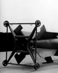
Another still image captured from the German Newsreel video on Youtube. This shows that the outward facing sides of the trolly braces
have edges and are not flat sided as per the kit. You can also see that the wheels appear to have only four holes as opposed to the six found on the kit wheels.
Also notice that if you decide to mount the missile on it's stands, the rudders should have some deflection. |
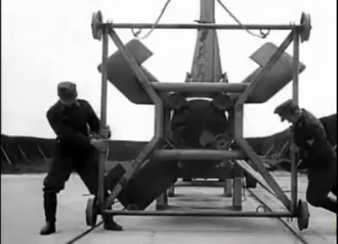 And a final still image again captured from the German Newsreel video on Youtube. This shows a few of the other discrepancies with the kit's trolly. First
there's the missing half-circle loops. If you look at the bracing/spokes running to the corners and compare that with the kit's representation, you can see that the kit is nowhere
near correct.
And a final still image again captured from the German Newsreel video on Youtube. This shows a few of the other discrepancies with the kit's trolly. First
there's the missing half-circle loops. If you look at the bracing/spokes running to the corners and compare that with the kit's representation, you can see that the kit is nowhere
near correct.
Also, on the missile itself, you can also see four large circular/octagonal (the exact shape can not be determined as they are covered with something cloth like) objects
in line with the control surfaces. The kit only uses a simple rectangular and flat extension from the control surfaces to represent these.
|
|