|
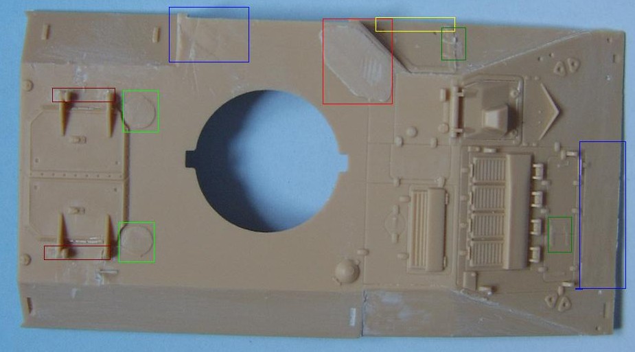
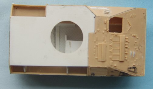
Hull corrections With the lower hull almost complete, we turn out attention to the upper hull. Here is where many of the faults lie and so most of the work centres around the upper hull. A lot of it is cosmetic, but there are also some major points that should be done to produce a better Warrior. As I have said before, it is up to you to decide how much of this you want to attempt, as only you will know your own "skill" level. I don't particularly consider myself to be a skilled modeler, but what I am is dogged, and will use perhaps unconventional methods to achieve my goals. I am a great believer in trying, and although it takes a few tries to get it right (as my dustbin will testify), just by attempting it you can possibly find a way that is easier for you, rather than sticking rigidly to the way described to you by someone else. The best way to start, is by removing all the offending items before rebuilding anything. This includes the engine access hinges, moulded on handles, the periscopes above the troop compartment (but not the circular mounting plates they are on), the troop compartment roof hatch hinges, the air intake to the left of the turret and the breather to the rear, the tool mounting bracket in front of the louvers. With these items removed you can now start to rebuild the hull.
In the picture above, the more observant of you will note that I have also removed the exhaust from the right hand side due to there being a detail error on how the side plates meet the glacis plate. This error is apparent on both sides of the vehicle, difficult to correct, and not included in this article. The exhausts will be replaced by using the exhausts from a spare hull top, obtained as a left over from the CMSC MRV conversion. 1. The first thing that needs to be done is the access panel to the left of the driver. The kit shows this hatch extending down to the lower edge, whereas it needs to be raised so that it ends 1mm before the edge. This is a fairly simple operation, done by shaving of the old detail and replacing it with plastic strip further up. The hinges for this panel also need to be replaced, making them 90 degrees to the plate rather than vertical. When replacing the hinges, they also need to be moved up slightly. The brackets for the spades will need to be rebuilt.
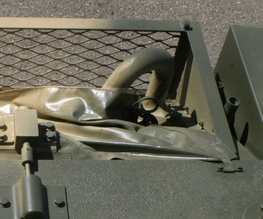
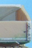
2. Moving down the left hand side we come to the air intake. This needs to be made higher and it was easier (for me) to remove and fabricate a new part than try to modify the kit. Interestingly the plate behind the intake, which is actually a plate to close off the intake, is the correct size and shows the correct height for the intake. The ends of this plate need to be cut square and the bits added to the intake itself [3].
4. Moving to the roof vent behind the intake, here it is the beveled edge that is missing rather than any dimensional error. Although it could do with being slightly higher, I got round this problem by using a spare one obtained from my spare hull top. However reshaping the profile also means having to replace the 4 bolts in the top.
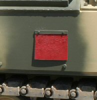
Immediately behind this on the vertical wall is a small exhaust. It is triangular in profile but square in plan [4]. A suitable piece of plastic should be glued in place, bearing in mind there is a stowage bin that also sits in this space. * This small exhaust does not apply to the MOAV or the BCP vehicles. 5. Moving around to behind the turret we come to the troop roof hatches. Here the hinges need to be replaced with plastic rod. Some may just want to replace the ends leaving the centre part intact as it is difficult to remove these without some loss of detail. However it would be better if the whole of it is replaced.
6. Forward of the hatches there are the two roof mounted periscopes. These have a distinct shape, not captured in the kit and must be rebuilt from scratch, unless you have access to the old 1/87 CMSC Warrior kit in Resin and White metal, which I believe is still marketed under United Fun on their web site. This kit had the periscopes as separate items, and although they were supposedly 1/87th scale they work well for the Revell Warrior (also for the loaders periscope on the Challenger). The 6 bolts on the circular mounting plates will have to be replaced before attaching the new periscopes.
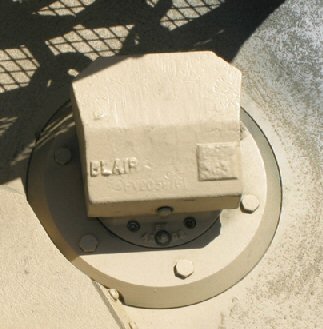
7. Moving forward from the periscopes we come to the fuel filler cap. This has the wrong profile in the kit and needs to be flattened slightly. Doing so will mean losing the latch detail, so this must be replaced.
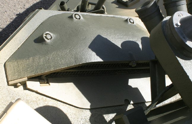
8. Moving further forward are the engine louvers. On the real vehicle these are covered by a mesh, which is not provided in the Extratech aftermarket PE set, but is I believe in the Eduard set. Also the armoured cowl is moulded in situ, making modification tricky.The armoured cowl, as it is moulded, is too short and too shallow, and needs to be built up in height using Milliput or other putty. The length, although not noticeable if not done, can be made up by adding plastic strip to the rear. This also has the effect of creating an undercut at the rear.
9. In front of the louvers are the horizontal engine access plate hinges which need to be replaced with hinges that are 90 degrees to the plate instead of the kit ones which are vertical.
10. There are 4 small lifting eyes around the engine plate that need to be drilled out using an appropriate sized drill bit.
11. In front of this comes the tool-mounting bracket. Some may want to replace this with more accurate tools. If so, it should be carved away and rebuilt from micro strip. Sometimes the bracket is empty, not because the vehicle has no tools, but because they would have been stowed elsewhere.
12. Moving down the right hand side, a demarcation line needs to be added between the 2 exhausts and 6 bolts need to be added to the front triangular portion.
A point to note. If the drivers hatch is to be replaced by either the CMSC part or a scratch built part, the easy way is to remove the whole hatch and rebuild a lip with micro strip for the hatch to sit on. 13. On the stowage basket, the moulded on mesh is aligned vertically, whereas it should be aligned diagonally. You can either elect to replace the mesh, or go the whole hog and replace the whole basket. A replacement basket would allow you to correct some detail. The lower edge of the basket, instead of being vertical as in the kit, should be at 90 degrees to the plate on which it is mounted. The basket can then be built up using plastic card for the sides, and strip for the front. The mesh can be placed behind the strip. You can also use the PE set from Extratech, but this has missing the detail at the bottom. If no cover is fitted to the basket, then a lifting eye, similar to the front pair, needs to be built and placed towards the rear of the vehicle towards the corner of the basket at an angle of about 30 degrees from the sides, with the actual eye being vertical.
The next thing to do is replace all the grab handles around the engine with ones made from thin wire, including the ones near the exhaust.
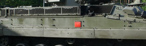
14. The main upper hull and sides, rear and lower tub can now be assembled, making sure that the upper hull and sides sit on the plastic strips added to the lower tub. These should stick out further than the sides. Once the glue has dried the plastic strips can now be trimmed to be flush with the hull, adding filler where necessary to ensure that there is a smooth finish to the sides. If done correctly there should be a small step in the side plates as shown on this picture.
Before
attaching the rear stowage bins to the rear plate, they will need
to be modified. The kit bins are too short and need to be lengthened.
You can either add the extra length to the back or to the front,
before adding the door. If you add it to the back, as I did, you
will need to remove the moulded on X on the sides and the 3 bars
on top, however the fastening latches can be retained. Doing it
this way you will have to modify the light clusters, as they will
now extend too far to the rear.
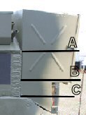
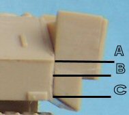
In actual fact the kit bins are also short in height, this is due to the light clusters being too large and at the wrong angle. Although this is not an exact science I hope the pictures below will illustrate what I mean.
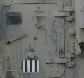
The left picture is the modified hull, the middle an actual vehicle and the right is as it is in the kit. As can be seen, the distance from the top of the light cluster to the angle in the side [A to B] should be greater than the depth of the light cluster [B to C]. In the kit it is the opposite way round. So in essence the whole bin and light cluster should be rebuilt, however that is only for the mentally insane, myself included. 15. Moving to the rear door, the door mounted fire extinguisher is located too low on the door. The lower attachment hole needs to be filled, and the upper locating lug from the bracket removed. This now makes the upper hole the location for the lower lug on the bracket. The door handle can be replaced with a micro strip version or carefully carved so that it stands away from the door. The door hinges themselves are vastly oversize and could do with being made smaller. If you do this then you can also replace the 2 rear towing eyes in a similar way to the front ones, as you will now have room.
16. Micro strip needs to be added to the rear on either side where the wheel units touch the rear plate.
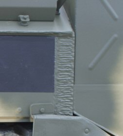
17. On each side at the rear a prominent weld bead needs to be added. This can be done with appropriate width micro strip then detailed to look like a weld bead.
18. A small lifting eye needs to be built next to the drivers hatch. This is the same as the lifting eye next to the roof ventilator on the left hand side. On some vehicles an extra lifting eye has been added to the top of the ventilator. It sits on a 5 sided plate bolted to the top.
19. With the sides now being deeper, the fire handle flap on both sides can be removed and rebuilt as a square, instead of the squashed items they are now.
20. Other items can now be added to the hull, such as the lights. The kit lights are moulded to the front grill which in itself is too small and could really do with replacing. This means however carefully removing the lights from the grill or sourcing them from somewhere else. The main light cage could do with careful thinning with a scalpel blade. The lights sit on a plate under the cage with side lights and indicators being mounted on a vertical strip. Behind the lights at the rear of the cage is a rectangular housing. From here emanate the cables for the lights. On the right side cage only there is a horn. This can be made from plastic discs and is attached via a bracket to the left-hand side of the rectangular housing. The Extratech PE light guard is too 2-dimensional, however the front light guard is the correct size and can be used as a template for new ones if you want to make them.
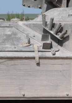
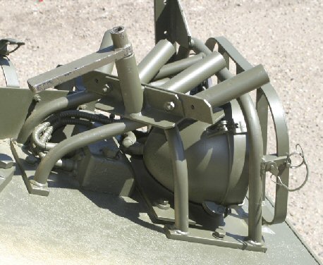
21. With this done other items can now be added to the light cage. First is the mounting for the mirrors. The kit part for this is correct so can be used. The next piece is the cam pole mountings. These are mounted on L brackets, with 4 holders facing horizontal and 1 vertical holder behind in the middle.
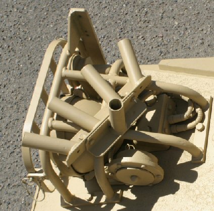
22. Four other sets of cam pole holders need to be made each with 4 holders mounted in a slight arc. One set is mounted with the holders pointing outwards between the exhaust louvres and the front of the side cage on the right hand side [13]. The next needs to be between the cage and the rear bin [13a] and then again on the left-hand side between the rear bin and the stowage bin [22]. The last is mounted on the left hand side where the NBC housing slopes back [2].
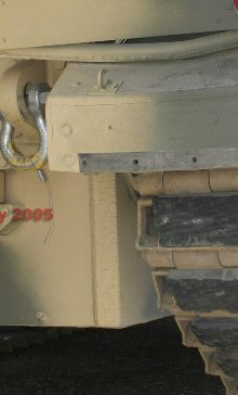
23. The other thing, if modeling a post First Gulf War or SFOR/KFOR vehicle without additional armour, the fittings for the armour needs to be added to the sides. On the left side this is 2 sets of 4 with an offset pair on the NBC housing [23], and on the right hand side there are a few more with 2 sets of 4 and 3 pairs with the same spacing, and 1 pair with a smaller spacing [23a].
24. Also to watch out for is that vehicles which have been Up Armoured also have 2 rectangular lugs welded in front of the drivers side access hatch.[24]
|
 [1]
[1] 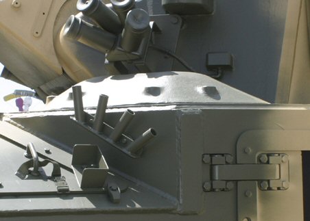 [2]
[2]
 [3]
[3] The plate for closing the intake
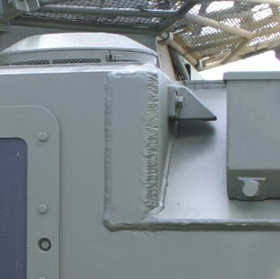 [4]
[4]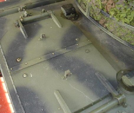 [5]
[5]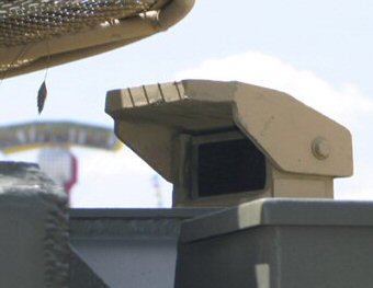 [6]
[6]
 [6a]
[6a]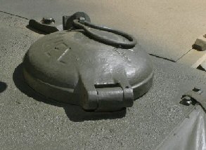 [7]
[7]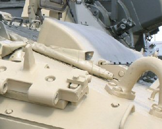 [8]
[8]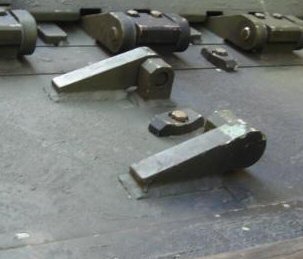 [9]
[9]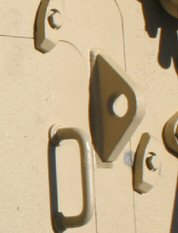 [10]
[10]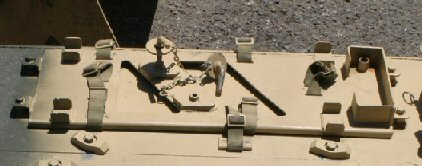 [11]
[11]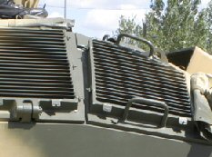 [12]
[12]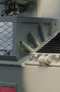 [13]
[13]
 [13a]
[13a]
 [14]
[14]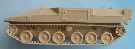 Unmodified
kit
Unmodified
kit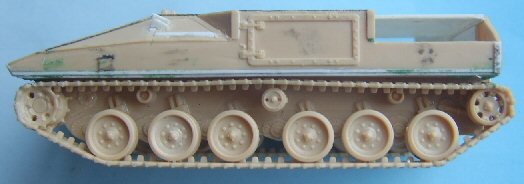
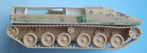
 Modified hull.
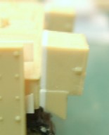
 [15]
[15]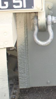 [16]
[16]
 [16a]
[16a]
 [17]
[17]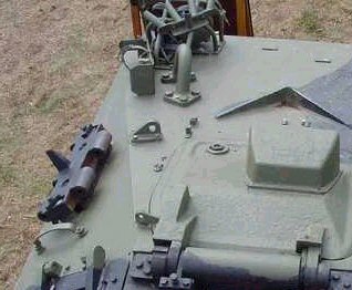 [18]
[18]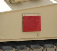 [19]
[19]
 [19a]
[19a]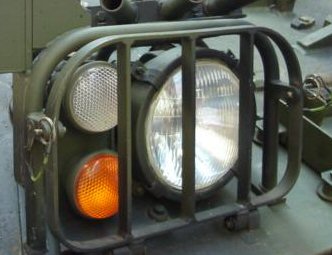 [20]
[20]
 [20a]
[20a]
 [21]
[21]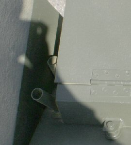 [22]
[22]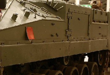 [23]
[23]
 [23a]
[23a] [24]
[24]