|
2014 IPMS USA Nationals were coming and what to build for the new combined scales scratchbuilt/conversion category? There are some criteria for this selection: it
must be unique/funky to attract attention; large enough to compete with the 1/35 models, and buildable.
None of my shelf queens could be ready in time and my existing list of want-a-builds did not excite me. While surfing, I found this Italian artillery piece from
World War One. Wow, can't be funkier than this one!
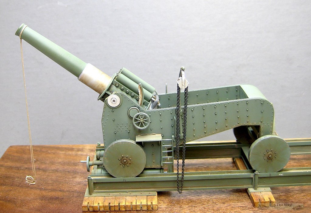
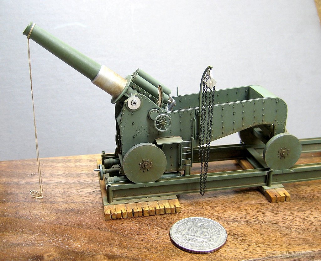
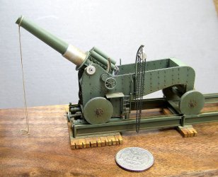
This artillery piece is the standard 305mm howitzer but mounted on a chassis and rail system designed by De Stefano which helped with the recoil and eliminated
the need to dig a hole for recoil clearance. The barrel is seventeen feet long and it stands, ground to trunnion about 12 feet. Weight was around 34 tons!
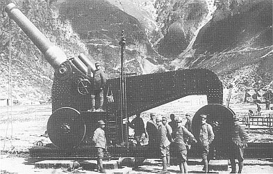
There is a resin kit by G B Modelli whose website provided a detailed side view drawing and some photos of their kit pieces that were very helpful in building my
model. More reference photos of the real thing were found by surfing the web, including the one copied for the model as displayed!
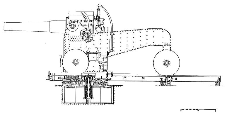
First, the side view drawing was enlarged until the gun barrel scaled seventeen feet in 1/72. This drawing served as the pattern for the pieces.
From the photographs, the details were determined. Each side appeared to be two pieces with a spacer joined by lots of rivets, bolts or both. The sides were
joined by two bulkheads, one under the gun trunnions and the other at the end of the loading platform. There was a floor for the loading crew, a floor under
the front bulkhead, and another "floor" under that, covering the horizontal portion of the bottom. At the bottom of the rear was a thick cross member to hold the pin
for the swiveling rear wheels. The gun barrel recoiled inside the cradle with the recoil chambers on top. That curved piece seemed to engage a hand wheel that
elevated the gun. Two cylinders were attached to the rail platform that somehow connected to the chassis. All this was worked out as the build progressed plus
little details too numerous to mention, just the first step in scratch building with little information.
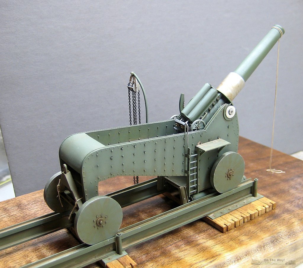
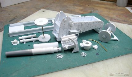
The build was broken down into components: the two sides, bulkheads to join the sides; wheels; fixed axle in front; swiveling axle component at back; gun barrel,
cradle with its trunnion mounts, recoil buffers and various attachments. The De Stefano rail system would be be three components: the rails, a separate piece
which slides between the rails containing the cylinders and the wooden timbers under the rails. The sides and bulkheads would be assembled, but the other pieces,
once made, were left unassembled until after painting.
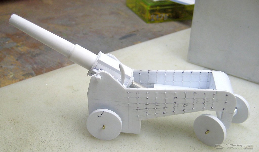
Each side consist of two pieces of 20 thousand sheet plastic cut to shape with 20 thousand square strips as spacers. A copy of the side view was laid over the
sides and a needle pushed through the plan into the plastic sides at the location of rivets/bolt. This was not completely satisfactory, so lines were drawn
to guide placement of the rivets/bolts.These were then added using round disc (39 thousand) punched from 20 thousand plastic sheet with a Waldron punch set.
Smaller rivet/bolts were made using my hypodermic punch (20 thousand) on 10 thousand sheet. After a few were glued on, a metal straight edge was used to straighten
the row, then continue applying and straightening.
The wheels are discs cut from plastic sheet using a very old (my father's) small divider spun on 20 thousand, then cut out, one for each side of the wheel.
The pivot point of the divider was drilled out as the location of the axle. Square pieces of 40 thousand were glued as spacers, 2 per wheel, rotated to
resembled the Star of David. The center of these squares were drilled out. All four components of a wheel were assembled using a brass rod in the axle
hole to center all pieces. After the pieces dried, the rod was removed.Then a strip of 10 thousand was wrapped around the perimeter of the wheel. Of the
four wheels, two matched but where larger than the other matched pair. Another wrap of ten thousand around the small wheels and everybody matched! A piece
of plastic tube represents the outer end of the axle. I forgot to add the grease fitting!
The axles are thick brass rod. In the back, the axle was encased in the plastic strips making the swiveling rear wheel assembly.
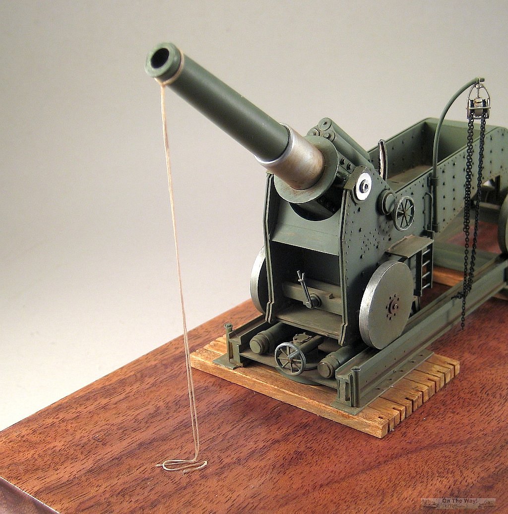
The barrel was made by telescoping pieces of plastic tubing glued together using slow drying crazy glue. This filled the gap caused by a slight difference in
diameter between the pieces and responds better to cutting and sanding. The center, bore, of the gun is K&B aluminum tubing, left longer at the breech end. The
taper of the barrel was roughly cut to shape then sanded with 220 wet and dry mounted on a stiff board, periodically checking for a straight taper and no flat spots.
I think the barrel assemble was chucked in my drill and spun at slow speed for the final sanding. On the real gun, the tapered part of the barrel stops at what
appears to be a straight larger diameter section. That was another piece of tubing with its front edge rounded. The straight section slides inside the "cradle"
The "cradle" was another even larger diameter piece of tubing which, alas, had a slightly greater inside diameter. A lengthwise strip was cut out and the gap
closed with liquid glue. Now there was a tight fit.
The cradle had a disc at both ends, a straight piece joining them on which were mounted the trunnions. It appeared from the photos, that this cradle was two
halves; separated vertically then bolted together. So a flat piece was glued top and bottom followed by a vertical piece added to the sides. On this vertical
piece were the bolts, a stiffener and the trunnions. The bolt heads and nuts were made from discs cut from hexagonal Evergreen rod and mounted on 5 thousand discs.
The recoil cylinders mounted on the flat area are more tubing with some added discs. The piston rods that slid into the cylinders were not installed until the
assembly stage.
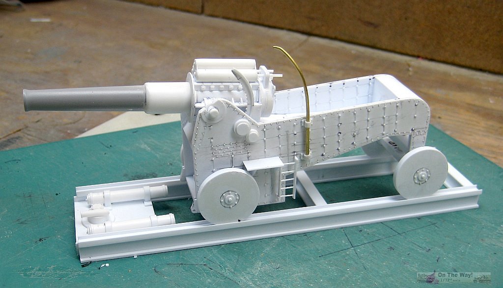
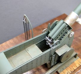
A prominent feature on the cradle is the elevating mechanism, an arc with a stiffener on the outside of the arc and the teeth on the inside. The arc was traced
from the plans onto plastic again with Pop's divider. On the inside, this scribed mark served as the centerline for drilling 23 thousand holes spaced 23 thousand apart. After all were drilled, a new sharp #11 blade cut on the scribed line and... teeth! Gentle sanding inside the half holes rounded the edges and cleaned up the plastic. On the model, some careful fudging allowed the elevating hand wheel mechanism to connect inside to the arc! Doesn't' work, but it does connect.
The gun breech was pictured in great detail in one photo. All that detail was copied with various sizes of plastic in two pieces, the breech which would slide
onto the K&B tubing and the breech block would slide into the breech. The breech had one large "ear" at the top for the recoil pistons to attach and two ears on
the sides. One was for a geared shaft to return the gun fully after recoil and the other was left empty in some photos so, the model left it empty!.
This completed the major components, now for the little details.
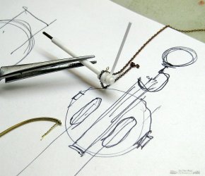
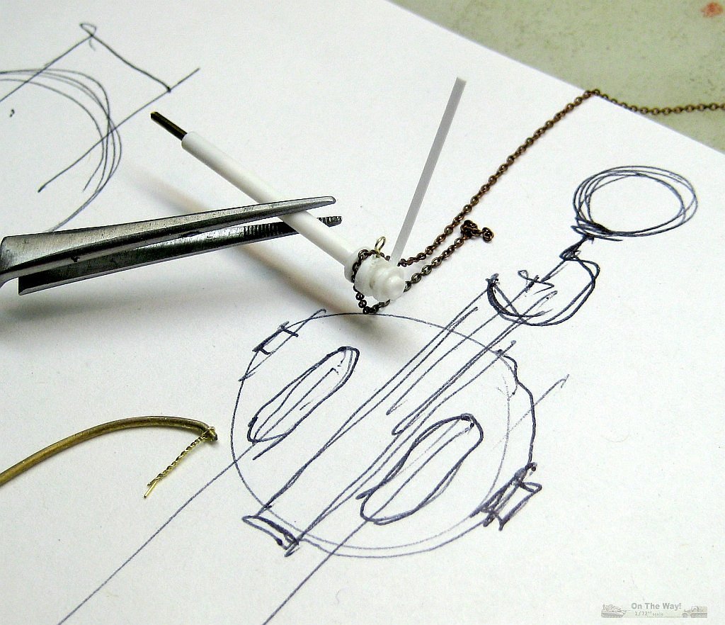
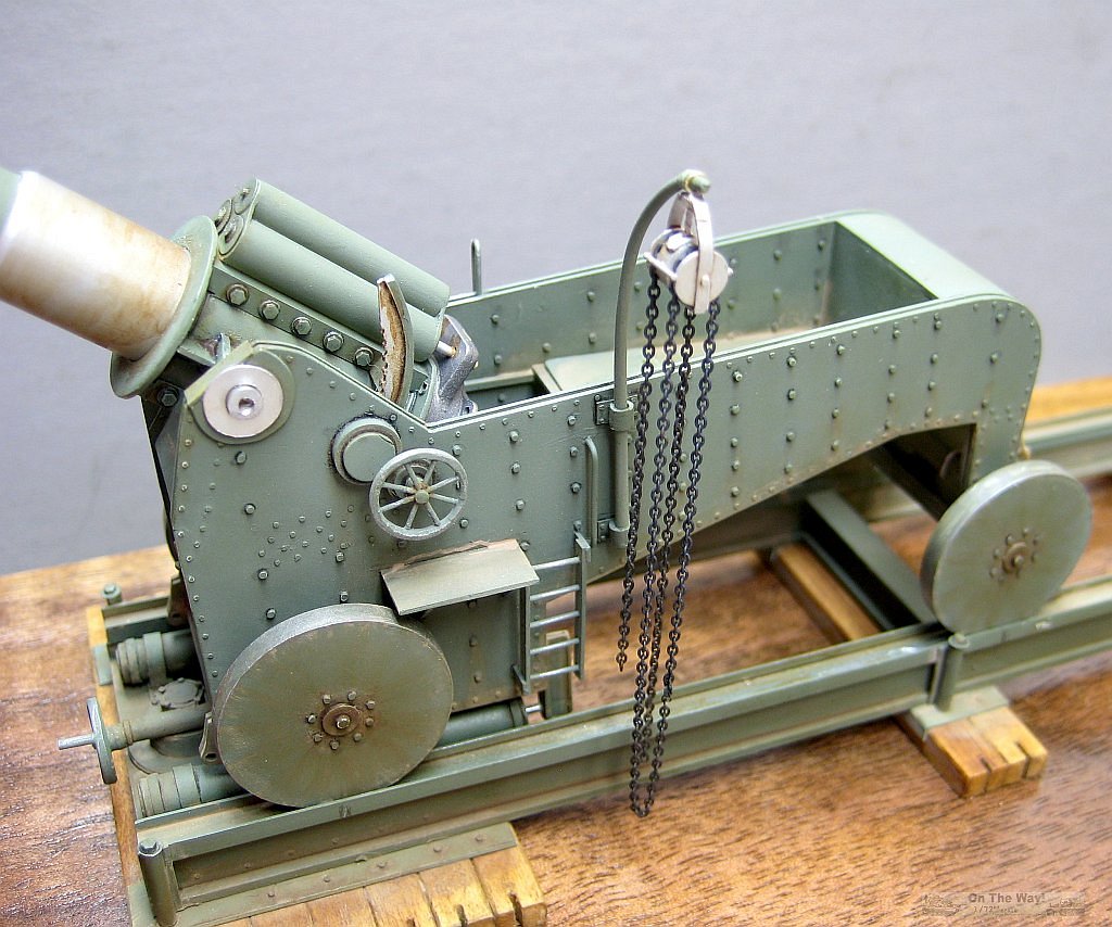
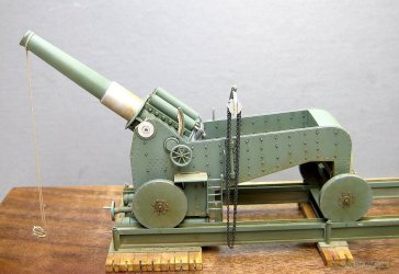
The crane is brass rod filed to a taper. The "chain hoist" is discs sandwiched together with plastic strip for hangers and wired twisted for the loops. The
chain is from a model ship source, colored using Blackit.
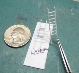
Ladders were a prominent detail. I used a jig to assemble the ladders. First two overlong strips of 15x80 were lightly glued together at their ends and that
end marked on both sides as reference. Dividers marked the location of the rungs. Holes were drilled for the rungs, with the drill always vertical! The sides
were separated, overlong 20 thousand rods inserted and the assembled ladder set in the jig to hold the side rails parallel with the rungs perpendicular. Then,
with it all aligned, Tamiya Thin glue was applied where the rung entered the side rail. Dry overnight; trim to length and perfect ladder!
Grab handles were made from 15 thousand brass rod and are another eye catching detail.
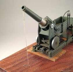
Rails were strips of Evergreen glued to make an "I" beam and then a "U" channel on top of the long rails. There is a round base under the rails, probably a
swivel base/turntable for side to side movement. One drawing shows this feature as a tub buried in the ground. Between the rail's recoil cylinders is a
device, either a winch to retrieve the chassis after recoil or to turn the rail on that base/turntable. Difficult to image how you could rotate something
this heavy and clumsy.
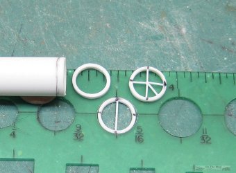
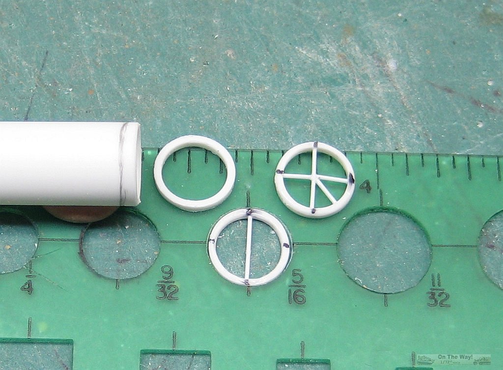
Handwheels are a ring cut from large plastic tubing with 10 thousand spokes... easier than it sounds. The ring cut from the tubing was rounded and placed in
a drawing template to mark four positions, each at 90 degrees. Then one piece of 10 thousand rod was cut to fit inside join two opposing marks and glued in
place. After it had dried, those dividers measured the distance from the other marks to that rod. Pieces were cut and glued in place. More pieces were made
and glued in between the spokes already in place. Don't attempt this without some reversible tweezers.
Handbrake for the front wheel brakes was another small detail that would add some wow factor, again cobbled together strips/rod of plastic. Wood timbers are just
that... strips of basswood, stained with oils. Platforms on each side are sheet plastic with bracing struts. Hooks were made to connect the rail recoil cylinders to
the chassis. One photo gave a glimpse of these stored inside the gun
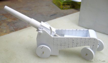

All the photos show a mono-colored gun with varying degrees of dust. Tamiya paints were mixed to create a grey/green light enough so the model would not disappear
on the contest table but dark enough to be believable! That base color was lightened many times as various parts were painted for contrast or to show fading on top
surfaces. Alclad was used for the metal areas. Oils were used as general area and pin washes. MIG pastels were applied as a slush and brushed away when dried.
This was repeated several times to build up dust in certain areas.
Greatest problem painting was the area between the two floors and aft of the front bulkhead.
With the components painted, the model was assembled. Why is there rope tied to the end of the barrel? It's a mystery but all the photos have it! The rope
came from a ship building fellow modeler.
Total build time was approx. 2½ months.
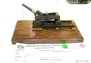
The base is a scrap piece of Walnut from a woodworking neighbor. I added a single piece of thick clear Plexiglas, as long as the base and higher than the gun
barrel, to protect the gun from being knocked around on the display table. That shield has now been removed. My model took a Third place in the new Armor
Scratchbuilt/Conversion Category at the 2014 IPMS USA Nationals.


|